Please do not laugh or flame me as I am sure this is going to be a really dumb question to most everyone,
I have a image of parts placed on a breadboard I am trying to duplicate this on breadboard heres my problem, On the image there is a usb power module. It shows a wire from positive to battery and negative to battery, Then it shows 1 wire from the usb connection end leading to switch.
Now if I was soldering this to a Pcb board I have no clue where this wire actually connects on the usb end. Please see image
The only stupid question is the one you don’t ask … If you don’t know the only way to find out is to ask.
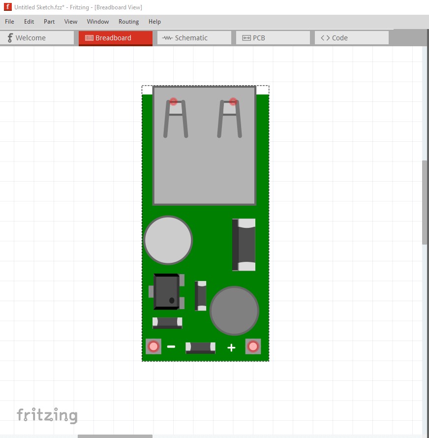
The image isn’t here. You can’t (I don’t think!) drag and drop images, you need to use the upload icon (7th from the left in the reply menu) to upload the image file. That said I can probably answer anyway. In Fritzing there are usually not active USB connections (the exception is USB plugs where the pins are broken out.) I expect you have a module that looks like this:
(which I made for someone a few weeks ago.) You will note the red connection dots in the USB connector. That is where the input connection in schematic would go. In real life the USB connector would connect to a USB port via a USB cable, but that typically isn’t shown in Fritzing. There are some breadboard only USB cables that will “connect” (only in breadboard not in schematic or pcb views) to the non functional USB port on a RaspberryPI cpu for instance (or any of the other CPUs that have USB ports) in breadboard for documentation purposes. The part pictured above is available here:
as 0.9v-5V-booster-usb-output.fzpz . Hope this helps, if not ask again til I (or someone else) gets it right .
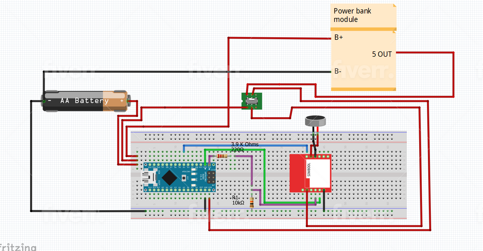
Ah! This is incorrect in several ways (the article that the converter came from will be worth reading because it describes basically the same setup.) He wanted the 800l as well as the power converter, but the power converter he had is both too low current (the 800l needs 2amps max and the converter is only 600ma) and the wrong voltage. The 800l maximum voltage is 4.2V and giving it 5V may damage it. It expects to connect to a 18650 type LIPO battery (there is a fritzing part for the 18650s) or a 2A capable boost/buck converter adjusted to 4V output to power the 800l. It is unclear to me if the 800L I/O pins are 5v tolerant or if you want to use a 3.3V nano to avoid level translation (I didn’t read the data sheet for the 880l that far.) I suspect the power bar module in the image isn’t in fact the USB converter that I posted, but rather an 18650 battery charger / 5V output converter module which needs to be able to provide more than 2A (because the Nano is going to draw current as well) and a step down circuit to get the 4V@2A for the 800l. It looks to me that the Power bank module in the image is not a Friting part (probably because they couldn’t find a part) but rather a note in the sketch with wires connected to it, and thus doesn’t reflect what the actual part is supposed to be unless there is a part number somewhere not shown. Ah! I think I see what is going on. If the switch is dpdt then it looks like the battery (which should be an 18650 rather than the shown AA) connects directly to the 800l (which is dangerous without a battery protection circuit! As LIPO cells will explode or catch fire if shorted!) to supply the needed 3.7 to 4.2V to the 800L and the converter wants to be a step up conversion module which coverts the 18650 3.7 to 4.2V to 5V regulated for the Nano. As long as the 800l inputs are 5v tolerant (you would need to check the 800l data sheet to see if they are or not, or if they expect 3.3V inputs) this should work fine. I’ll have a look and see if I have a Fritzing part for a 18650 to 5V power converter or not. I may have made one in the past (that should also give you a part number for the part you need.) There are a bunch of modules on ebay and others that take a 18650 battery and convert it to 5V regulated to power USB, I don’t remember if there is a Fritzing part though.
I really want to start from scratch and reading your replies makes me want to even more, The project I am trying to build is a device that has a sim card with a phone number , when I call the number I can hear what is being said from people near the device, Without them knowing I am listening
I think that would be a good bet , I just read the Sim800l datasheet and it is even worse than I thought. The max logic input voltage is 3.0V (not even 3.3V) so even a 3.3V Nano would need level translation (they suggest resistors, and I don’t know that the breakout boards have them.) It appears the module itself is running at 2.8V internally. The max input power supply voltage is 4.4V max so a direct connection to a 18650 should be OK, but a 5V supply is probably not OK. To be safe as noted you need a battery protection module between the 18650 cell (which typically has no protection) and your circuit. There is a Fritzing part for the tp5100 module and that may do (it I think both provides protection and charging for the 18650.)