I have a project with an ESP32, and honestly, I would like to design a PCB, but I have no knowledge of electronics—I’m a programmer.
I made a working board using my very basic knowledge and pre-built modules, so I could just connect everything without dealing with individual electronic components.
My question is: Can anyone here help me produce a PCB with the following features?
ESP32-WROOM-32 (30 pins), which should be connectable/disconnectable using female headers.
Three 5V relays, each connected to a different GPIO.
12V DC input.
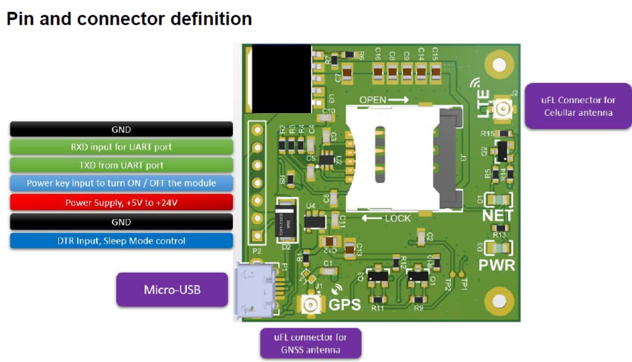
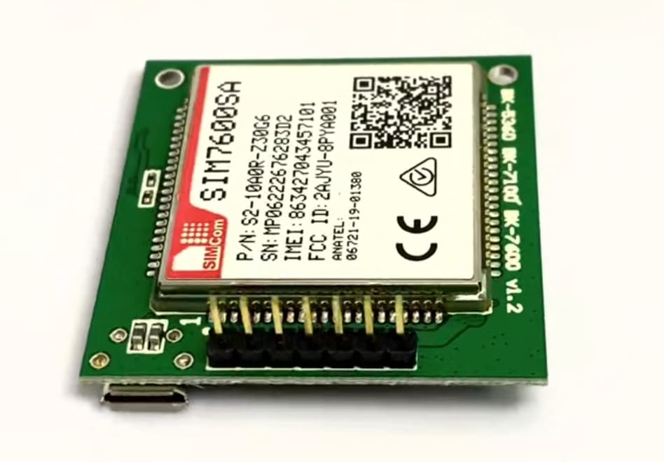
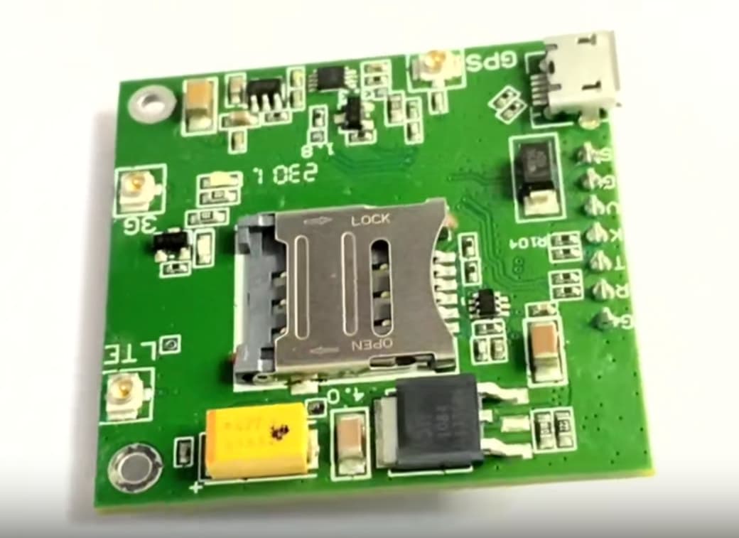
SIM7600SA module, which should also be connectable via female headers.
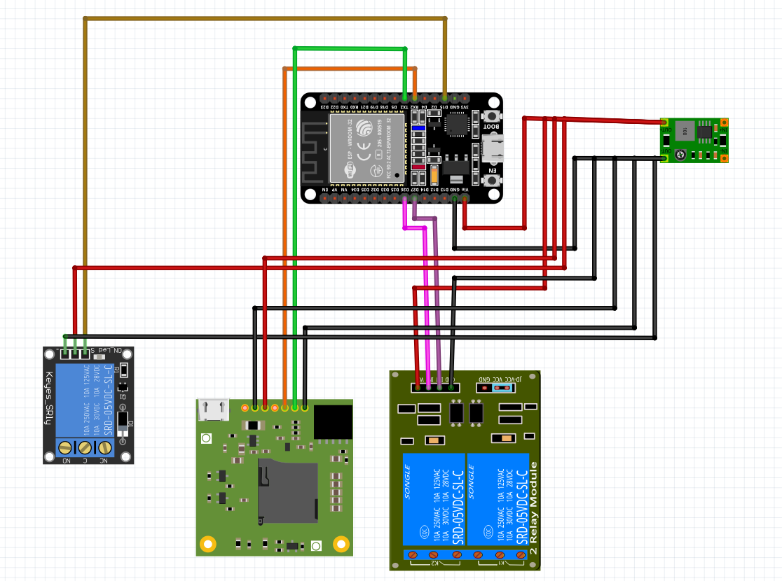
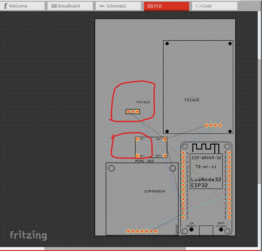
Here is an example of the schematic I made and that is currently working:
I currently connect 12V 2A and use a voltage regulator to power everything. My idea was to have one of the relays use 12V to connect a siren, but that’s not included in the schematic because I take the 12V directly from the DC connector.
In any case, everything works as it is, and it’s properly connected, though I’m not sure if it’s the best approach. As I mentioned, I’d really appreciate help with fabricating the PCB, since I’d like to order it from PCBWAY.
Also, if anyone needs help with programming, I’m happy to assist!
Assuming you want to use the modules (as opposed to bare components which would be a lot more work) you current sketch should make the parts appear in pcb view. You then need to move them in to an acceptable shape and connect then by clicking on the rats nest likes (or use autorouter although it usually doesn’t work well) to route the pcb. Upload the sketch (the .fzz file, upload is 7th icon from the left in the rely menu) and one of us will look it over for errors.
Hello Peter, thank you very much for your willingness and support.
I would really like to do it with basic components, so I don’t have to use wires, just female headers for the ESP32 and SIM7600SA. However, I honestly have no idea how to do it—I don’t know anything about electrical or electronic components. I only know very basic things, and I’m afraid of making a schematic that might damage any of the components I connect.
Anyway, I’m attaching the .fzz file. The downside is that in the PCB section, the SIM7600SA connector doesn’t look right.
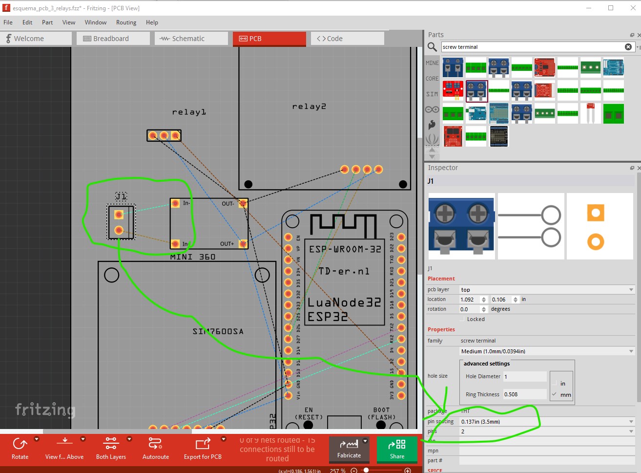
The mini 360 power module has no input connection. You would need to add either a 2 position screw terminal to connect wires to it or a 2pin header (the screw terminal is a better bet.) As well the 1 channel relay module doesn’t have a size in pcb (just the header terminals) and is a different size than the other 1 channel relay modules with Fritzing parts. Assuming you what you have is a keyes SR1Y which looks like the image and size of the part in breadboard I can add the correct size silkscreen in pcb to that part. If the modules you have are working, I would say the best bet is to continue using them. It is possible but fairly complex to replace them with components because they have internal optoisolators and other circuitry that we would need to copy and the chance of an error (with the result the board doesn’t work) is fairly high. Unfortunately the current 1 channel relay board isn’t the size of the Keyes SR1Y boards I can find on the net. The Fritzing part’s breadboard image is 24mm by 32.5mm but the size listed for it on a site selling it is 24 x 40mm so the best bet is likely to measure the unit you have and post the measurements and I will adjust the silkscreen values to match what you have. Here is an image of the board with the screw terminal added
doing this would mean you would need to buy a 2pin 3.5mm pitch screw terminal (they should be easily available) to install on your board. The power source would then connect via wires to that screw terminal to power the mini360. As to the SIM7600SA that appears to be the part by Raptor and I think it is probably correct (I checked it for him, but neither of us has an actual board so it could be wrong) why do you think the connector isn’t correct? As well, you are aware the pcb will come unassembled and you will need to solder the various headers and parts to the bare pcb? As well as noted earlier you will likely need to unsolder the right angle headers from the relay boards and replace them with headers on the bottom of the board to connect to your pcb.
Thanks for the clarification! I’d rather use a barrel jack for the power input instead of the screw terminal—would that work? About the SIM7600SA, at first, I thought the connector was wrong, but after checking again, I think it’s actually fine. Also, I know the PCB will come unassembled, and I’m comfortable with soldering and desoldering, so making those adjustments won’t be a problem.
I also wanted to mention that I understand the work involved in designing everything from scratch, so I’ll follow your advice and stick to using the preassembled modules for now. That way, I can avoid unnecessary complexity and ensure everything works as expected.
Let me know if there’s anything else I should check. Appreciate the help!
Yes there are barrel jacks in core parts and you could eliminate the mini 360 regulator if you used a regulated 5V or 3.3V wall wart in to the barrel jack although you may still need it if you need other voltages.
How much voltage and current are the relay outputs dealing with? A good alternative to relay is a solid state relay. They have no moving parts to wear out unlike a relay and are typically opto isolated. There are several with Fritzing parts available but only spst (your relays are spdt.) These folks appear to make a spdt SSR though although they look to be the only ones to do so. If you are only using two wires to the output section of the relay (rather than all three) a spst SSR should do you as long as the voltage and current match the output draw.
Both relay modules could be replaced by 3 of them they may be expensive though, there max load current looks to be 40A and 24 to 480V (40 A requires active cooling though.) or by likely lower cost spst SSRs if that will do.