Turns out the part you have is not correct. It is showing in breadboard as the 2nd fc-51. The correct part is available here (I thought it looked familiar, I made it for someone a couple of years ago.) which matches the image in breadboard above.
No your pin connections aren’t correct (in the Fritzing sense, I have no idea how they are supposed to connect to the Uno.) A Uno should do as long as it has sufficient memory to run the code and enough I/O ports to accommodate all the sensors. You need to figure out what should go to what pins on the Uno and then insure that they are correctly connected in Fritzing. Clicking on a pin will light up everything that it connects to yellow. At present as noted schematic is a mess and you have a short from 5V to ground somewhere in schematic. You need to find and eliminate that and then make sure everything is hooked up correctly to match whatever software is running this.
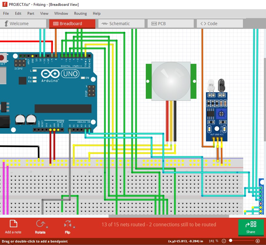
This is an example of both the ground/5V short and the pins lighting up the connections.
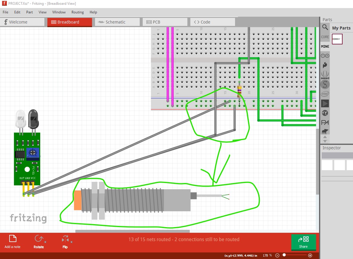
This is the correct part copied in the sketch. Its connections (there are only 2 instead of the 3 on the current one) need to be wired to the correct pins (I have no idea what those pins would be though.) The best bet is to completely wire breadboard and then use the rats nest lines in schematic to route that.
Peter