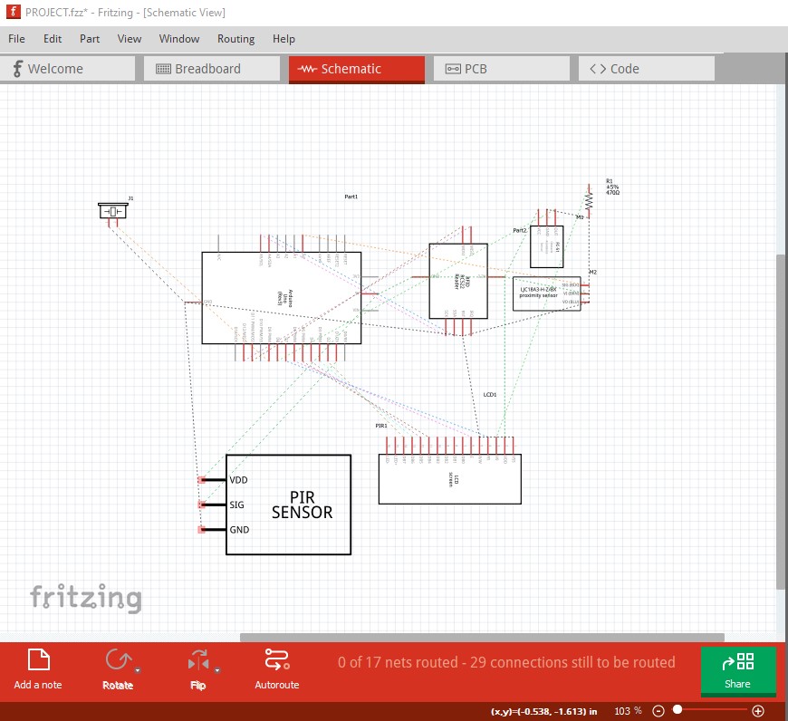
here is my file and please let me know if my connections and pins are right or incorrect. it also says 12 of 15 nets routed - 9 connections still be routed in breadboard. please help me out thank you
PROJECT.fzz (77.2 KB)
here is my file and please let me know if my connections and pins are right or incorrect. it also says 12 of 15 nets routed - 9 connections still be routed in breadboard. please help me out thank you
PROJECT.fzz (77.2 KB)
@vanepp hello leader can you please help me on this, it’s our last project in our sophomore year, thank you
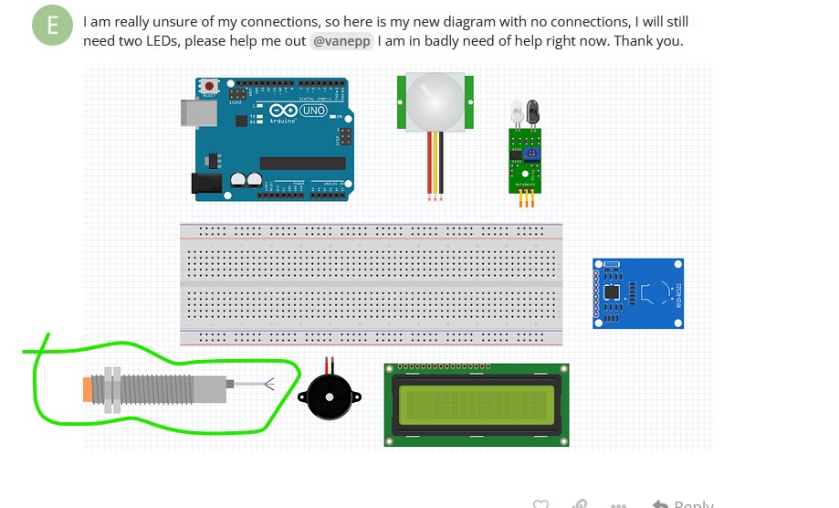
I am really unsure of my connections, so here is my new diagram with no connections, I will still need two LEDs, please help me out @vanepp I am in badly need of help right now. Thank you.
You have a number of problems.
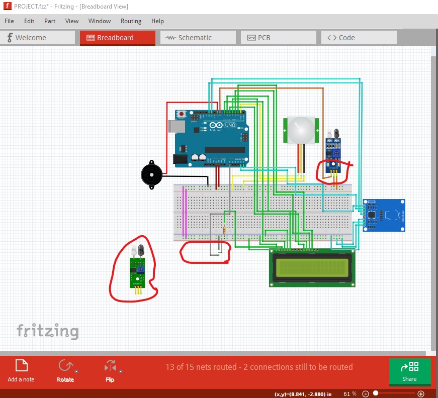
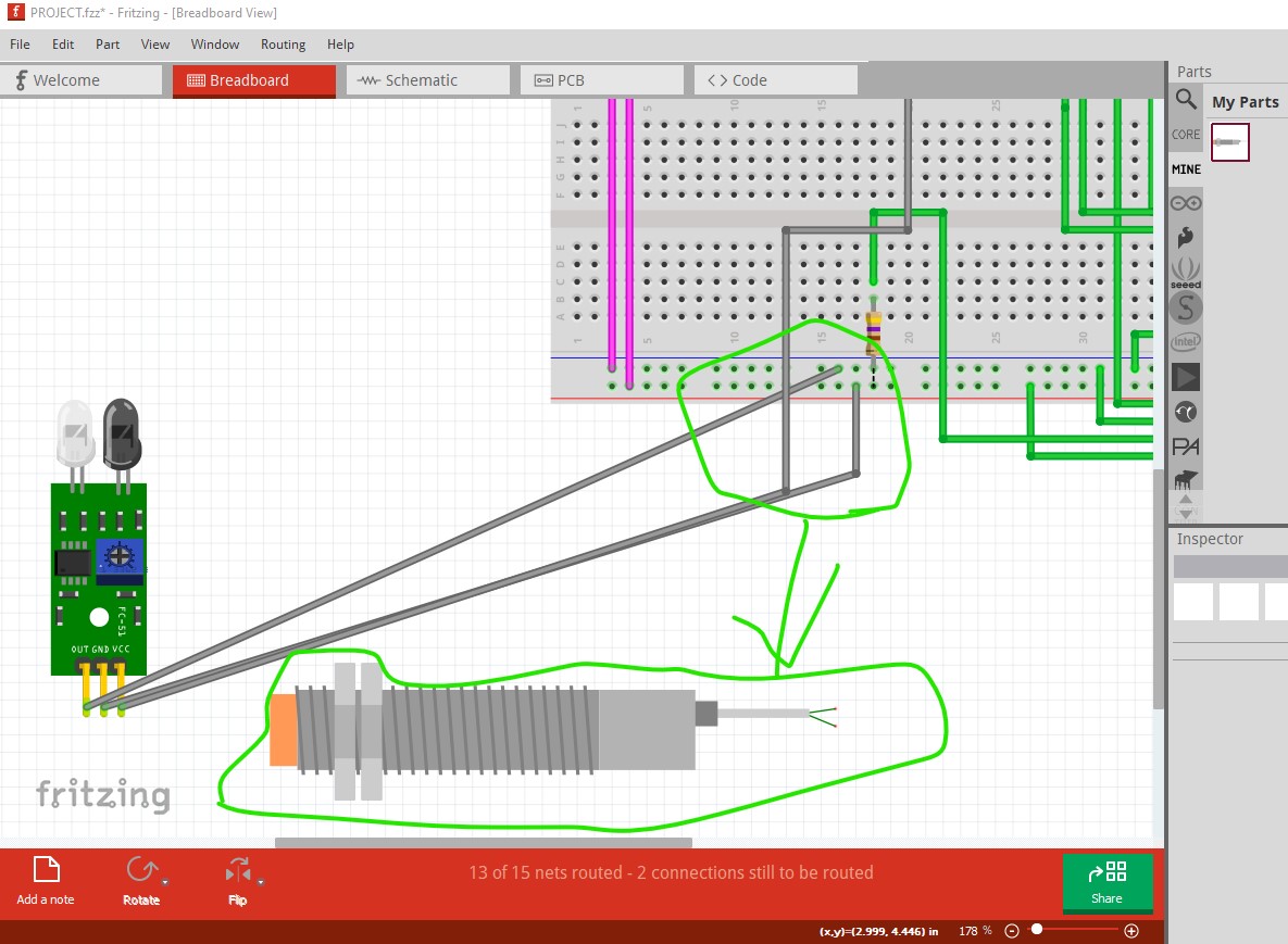
The part circled in green is missing from your sketch. There are two possibilities there, the part is misconfigured, or it hadn’t yet been added when the sketch was saved. If it is in the sketch please upload the .fzpz of the part (upload is 7th icon from the left in the reply menu) and I will fix the part.
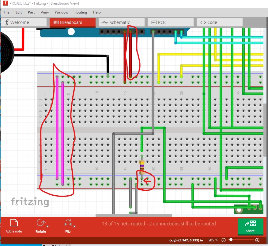
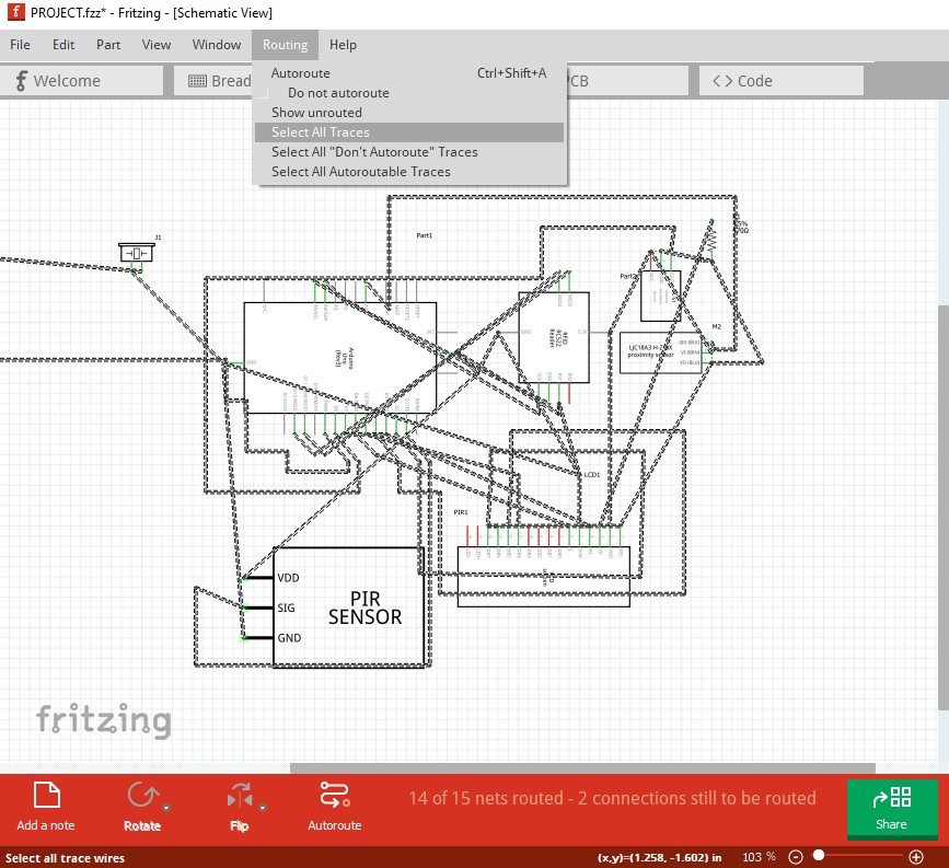
You need to correct the wire colors (although they won’t hurt anything) ground should be black not red on the top the two cyan on the left should be black and red to reflect ground and 5V. The rats nest line on R1 at the bottom indicates the short from power to ground (possibly introduced in schematic which will reflect in to breadboard. Schematic is a mess so I won’t even start there. Although removing all traces like this corrects routing in breadboard indicating a mistake or mistakes in schematic is what is causing the short.
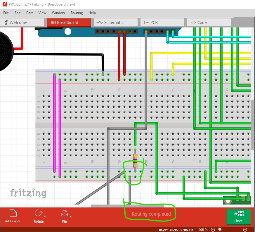
then hit the delete key to remove all traces.
which “fixes” (as there are still errors noted above) the short in breadboard.
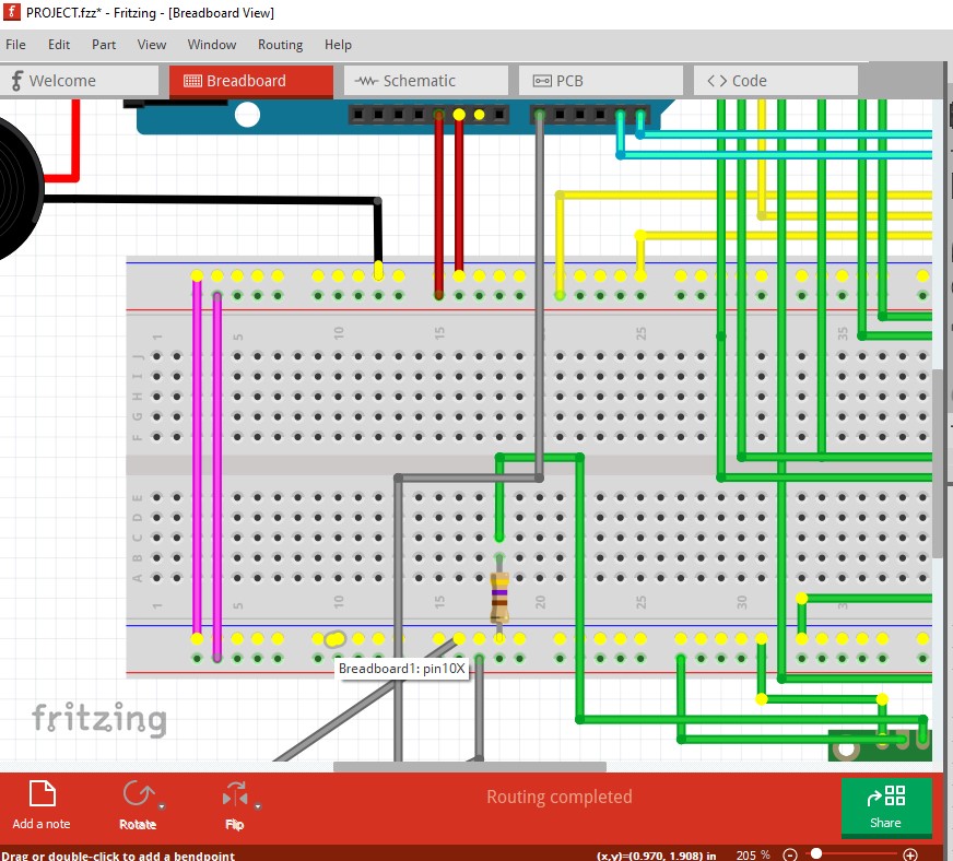
here I clicked on the ground pin with the green arrow and as you can see there is a short between power and ground.
with the schematic traces removed ground is separate from 5V (as it should be!)
Peter
hello. thank you so much for the help, i really appreciate it. is there no problems and errors in there now?
After the traces are removed in schematic, breadboard is OK, but there are still problems. As noted one part is not present but I don’t know it that is because it wasn’t in the sketch or because the is a problem with the part. If it should be in the sketch it was not included in the temp parts bin but that may be because the part is mis configured. If the part should be in the sketch but is not if you upload the .fzpz file from the part I can probably fix it.
Peter
here is the part that i got off of the internet. thank you so much for the help, it really means a lot to me
LJ18A3-H-ZBX.fzpz (4.7 KB)
are my pin connections correct? and also i have another question, since i have 6 sensors, is it really okay for me to use arduino uno or should i use arduino mega instead? thank you
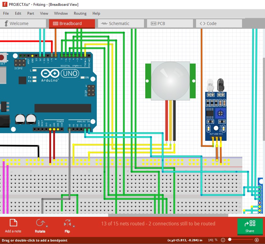
Turns out the part you have is not correct. It is showing in breadboard as the 2nd fc-51. The correct part is available here (I thought it looked familiar, I made it for someone a couple of years ago.) which matches the image in breadboard above.
No your pin connections aren’t correct (in the Fritzing sense, I have no idea how they are supposed to connect to the Uno.) A Uno should do as long as it has sufficient memory to run the code and enough I/O ports to accommodate all the sensors. You need to figure out what should go to what pins on the Uno and then insure that they are correctly connected in Fritzing. Clicking on a pin will light up everything that it connects to yellow. At present as noted schematic is a mess and you have a short from 5V to ground somewhere in schematic. You need to find and eliminate that and then make sure everything is hooked up correctly to match whatever software is running this.
This is an example of both the ground/5V short and the pins lighting up the connections.
This is the correct part copied in the sketch. Its connections (there are only 2 instead of the 3 on the current one) need to be wired to the correct pins (I have no idea what those pins would be though.) The best bet is to completely wire breadboard and then use the rats nest lines in schematic to route that.
Peter
hello, i already tried downloading that part and i need the LJ12A3-4-Z/BX inductive proximity sensor, the one that i have already bought. also, i don’t really know of the correct connections between Uno pins and the rest, and i can’t find the blue ir sensor and i used the green one because i thought it must’ve been similar, though i bought the blue one. here i made another diagram with no connections yet and arranged the schematic first. i hope you can help me out. thank you.
empty.fzz (52.5 KB)
Here is a proper part for the LJ12A3-4-Z/BX sensor
LJ12A3-4-Z_BX.fzpz (4.7 KB)
Here is a copy of your sketch with the new part added and some stuff moved around in schematic. Now you need to populate all the sensors and wire it as it should be.
empty1.fzz (31.5 KB)
Peter
Thank you. Can i ask for the copy of the previous file? Thank you so much
What previous file? Pretty much everything that exists is here somewhere.
Peter
the file named PROJECT that you recently opened. thank you.
It is available for download in the first post of this thread. I didn’t keep a copy of the one with schematic traces removed. You can recreate that by doing routing->select all traces and hit the delete key in schematic.
Peter
no copy of the PROJECT file that has Routing Completed?
No. That copy came from removing all traces in schematic which eliminates the short between gnd and 5V. You can achieve the same result by doing the same thing. The sketch is still broken in a variety of ways but routing completes.
Peter
@vanepp My perspective on this thread, is he is trying to get you to do the homework for him. That is where it started. Nothing to do with bad parts or bugs about bogus ratsnest. The wording is that he does not know where the connections should go. Not that Fritzing is doing something unexpected.
I’m aware of that which is why I haven’t been doing more than giving him the tools to do the job if he chooses. Some of his parts are indeed broken and he won’t be able to fix them.
Peter
I think you guys have misunderstood something. I don’t really know if my pins and connections are correct so I am trying to ask help if they are correct (which I just followed the instructions given to me). And you’re right, I don’t know where the connections should go. That’s all I want to ask help for (and to why my routing isn’t complete yet). Which is why I need answers that could answer my questions. I hoped that cleared up the misunderstanding here and I don’t want to be misunderstood. Do not assume that I am doing this to get you do it for me. Nakakaputangina ka tanginamo.