Im making a Microbit class for a workshop and i cant find any parts that looks like it and the wiring were all mismatched and the module looks like this
Please help i kinda need the part urgently as i had to present a draft by monday TvT
Im making a Microbit class for a workshop and i cant find any parts that looks like it and the wiring were all mismatched and the module looks like this
Please help i kinda need the part urgently as i had to present a draft by monday TvT
I dont have this Part but when searched online, someone made it but the file was not accessible
In sufficient information to do anything with. We would need a web site for the exact part you want with physical dimensions and connector information to do anything about finding or making a part. The template (which you appear to have delete) in this category asks for the needed information.
Peter
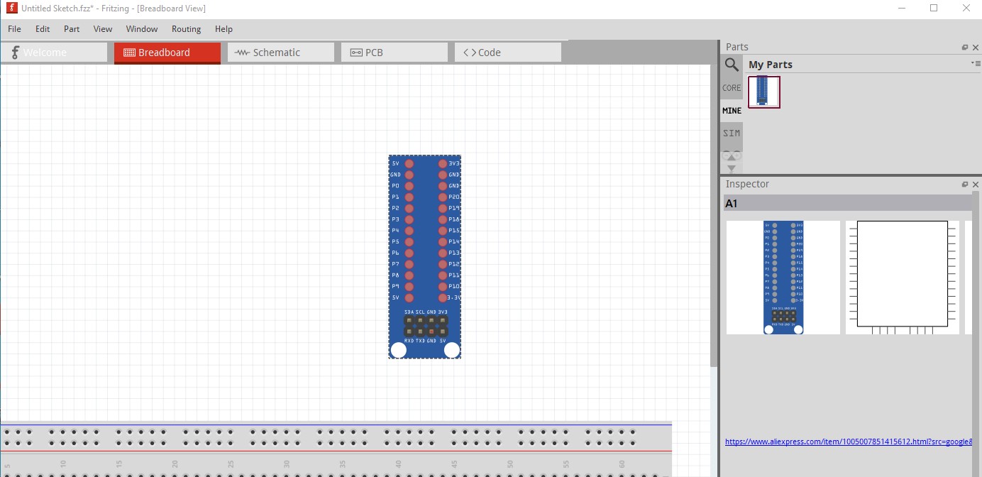
You were lucky and a search for the board name came up with this site which has sufficient information to make a part.
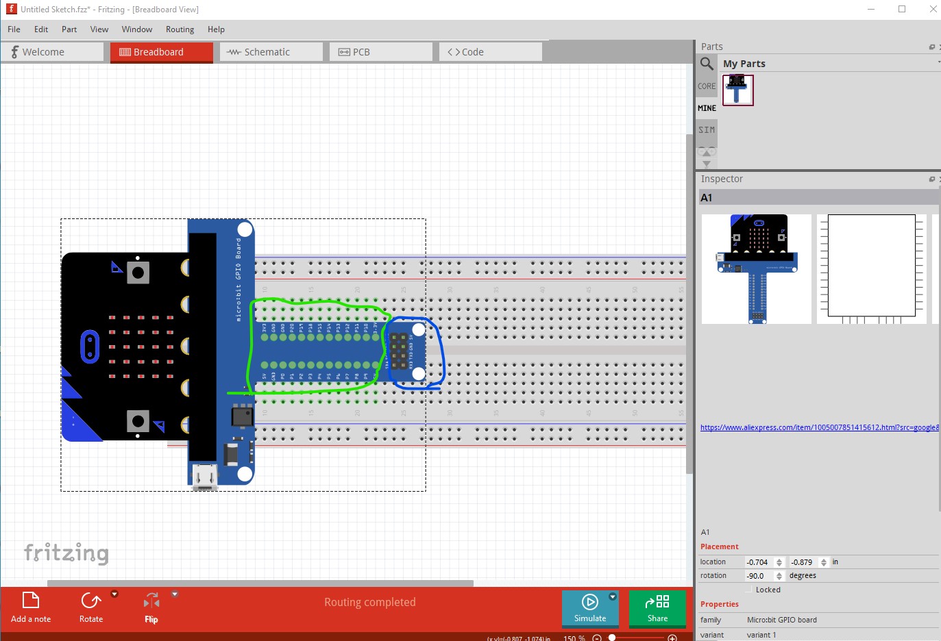
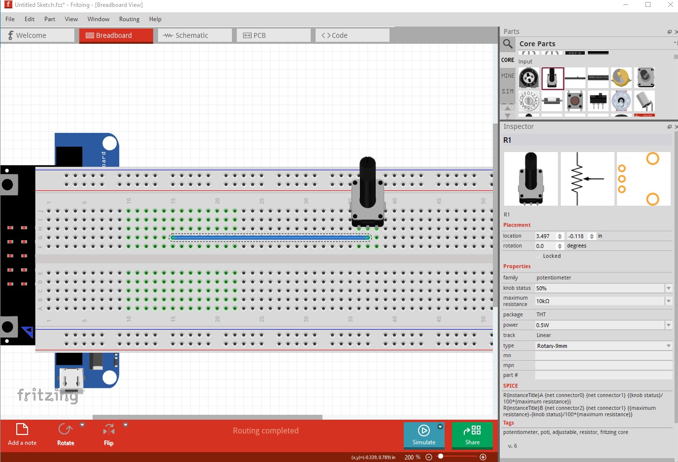
which resulted in this part, which has a few limitations. Pcb view has been suppressed as not useful, but breadboard also has some issues (due to how Fritizng works,) The area around the part will normally block connections to the breadboard.
here the green pads indicate the part is connected to the breadboard, but the square around the whole part will block you from making connections to the breadboard.
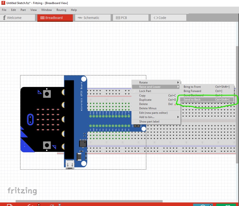
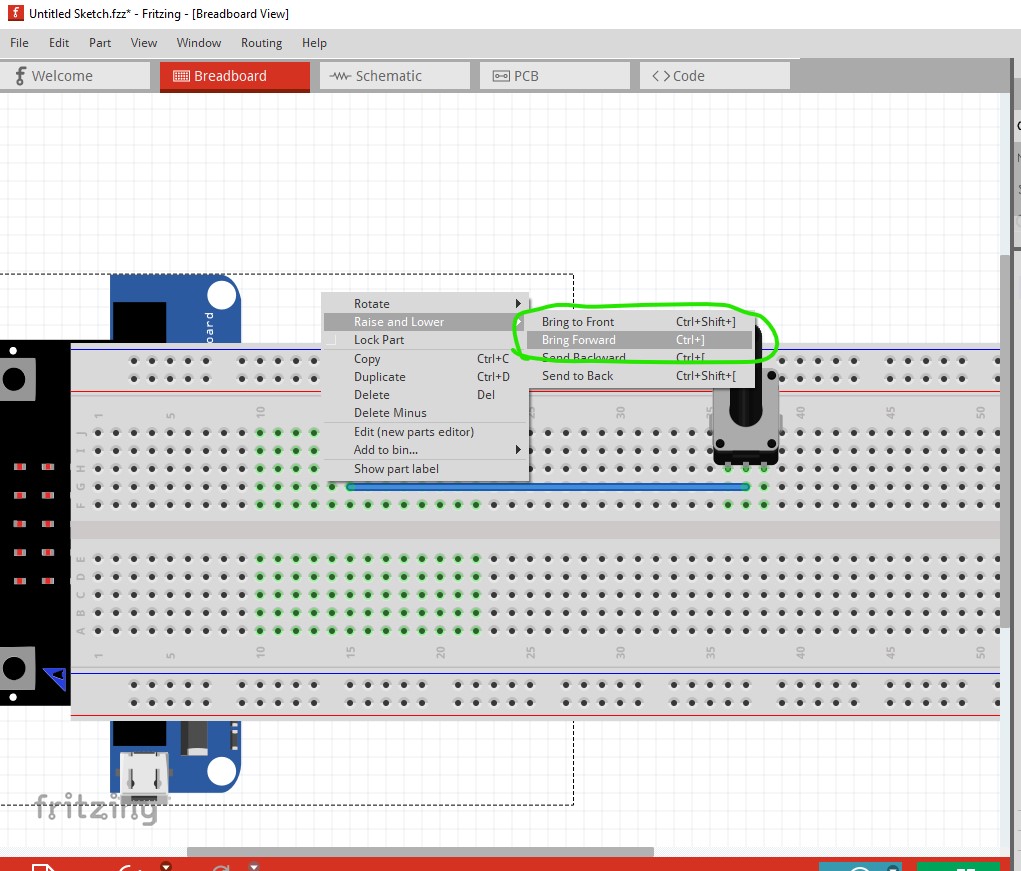
To make such a connection you need to do this: right click on the part and select “send to back” and click on it.
That sends the part to below the breadboard (the part is specially configured to be able to do this normal parts won’t go under the breadboard.)
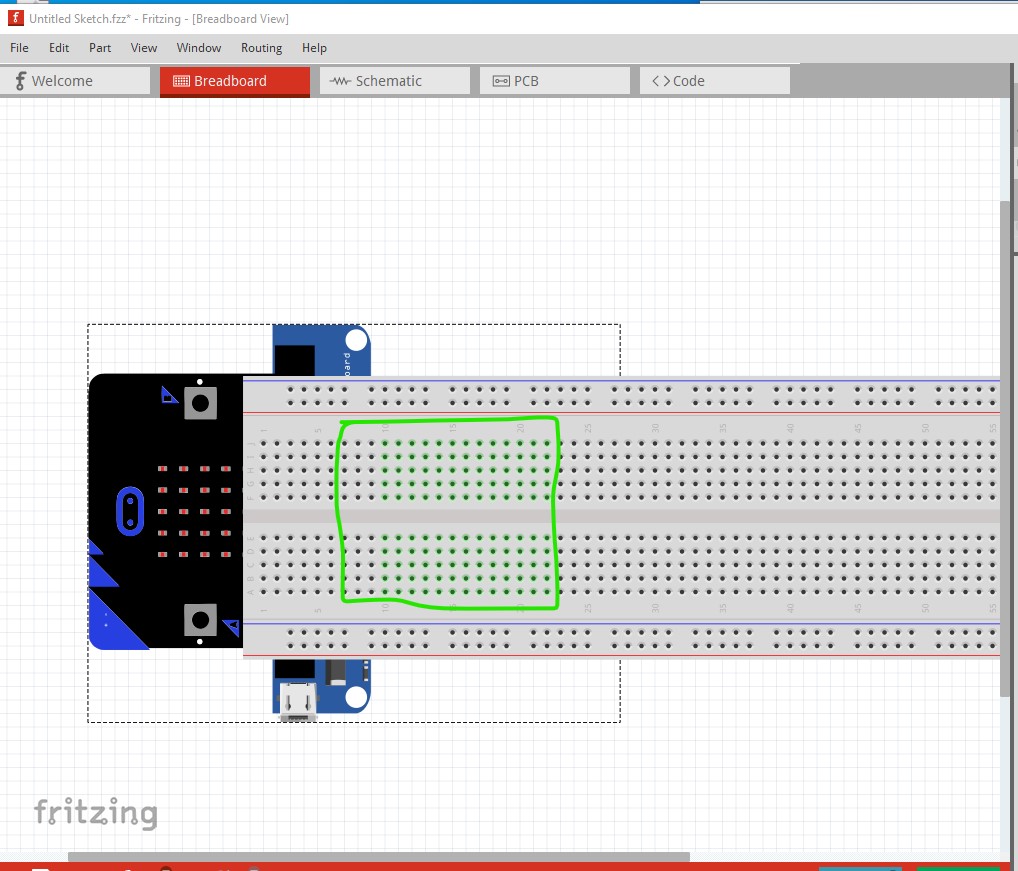
This is somewhat undesirable because you can’t see where the connectors are (except they are colored green as connected) but you can connect wires and components to the breadboard like this:
then
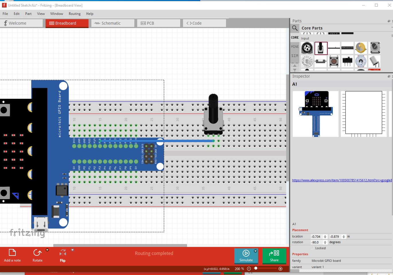
right click on the part again and select and click on “send forward”
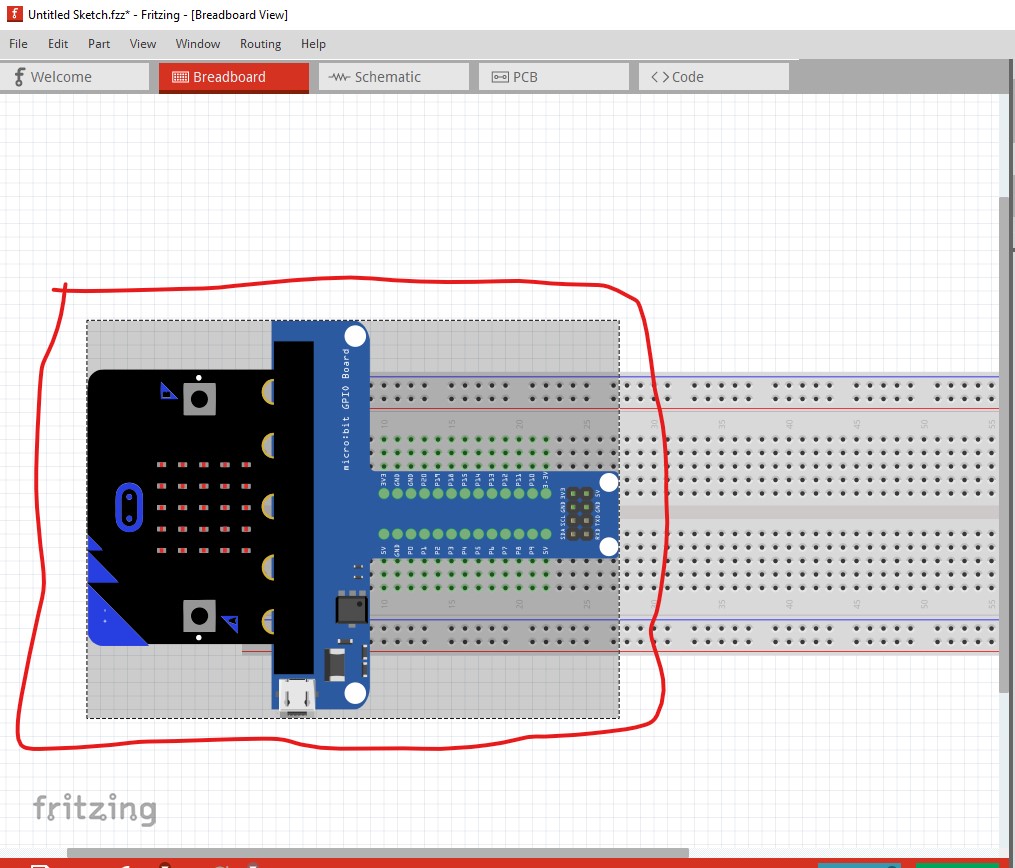
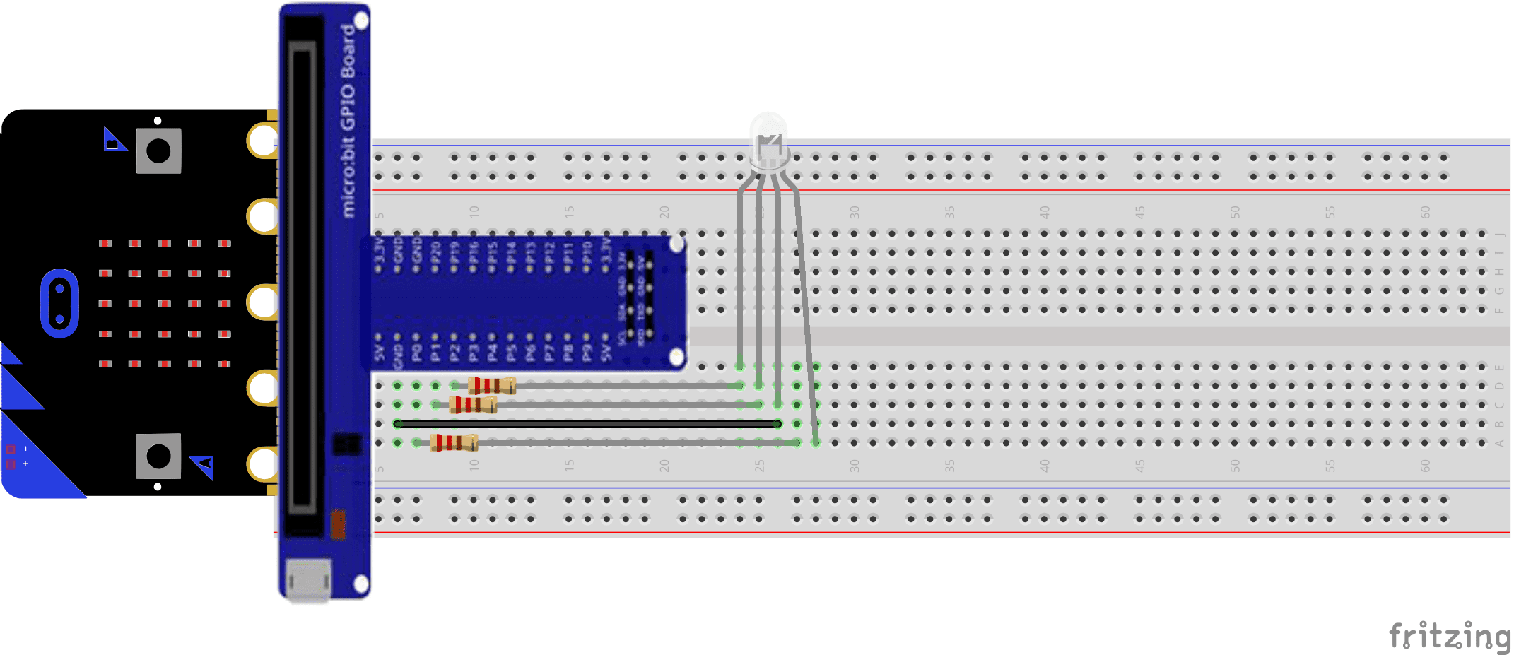
That produces this
which will show how the connections should be made for documentation purposes such as lecture slides. It isn’t ideal but is as good as we can do. Here is the part
microbit-gpio-board.fzpz (19.5 KB)
hope it helps (although it may also be too late as it is now Sunday here …)
Peter
Just nice, I hope, as it’s Monday, 11:26 am here
But if you live in Australia, it might be too late…
You’re a life saver!! luckily i can finished it by 5 over here in malaysia ![]()
![]()
@vanepp To get past those limitations, would it be possible to make that as 2 parts, one vertical, the other horizontal? There doesn’t seem to be any connectors in the bigger piece. Or even just make the horizontal piece as a part and place the other as an image? The new limitation being getting them to stay ‘linked’ when moving the part.
Next ‘trick’ that might work, would be to adjust the graphics position and viewbox, so that the non-connector part is outside of the viewbox. I think the other content will still render, but the ‘bounding box’ that is hiding the breadboard connectors might shrink to match the viewbox.
Thanks for the suggestions! I’ll experiment and see if I can find a solution, because the current one is ugly!
Peter
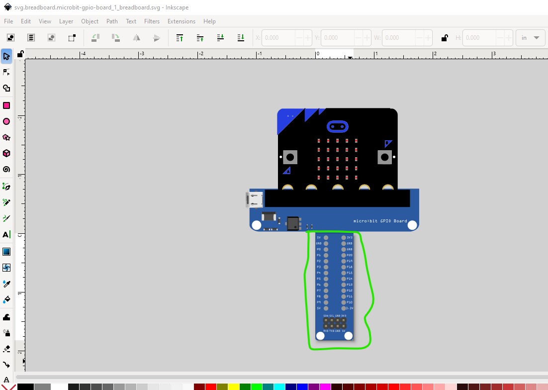
Good thought, but it truncates to the viewbox.
where the svg looks like this (with the viewbox in green)
Two parts may do it but syncing them will be a problem I expect. As ugly as the current solution is it may be the easiest answer.
Peter
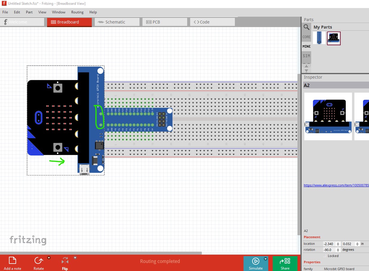
OK, following @microMerlin 's suggestion above I have made a marginally better two part solution. It breaks the part in to two pieces like this
The right most one has two connectors (only for alignment they don’t actually do anything) which you can let snap to grid position for you by moving the part to the left from this position and a part that implements the short part of the T with the correct connectors (which will allow you to connect wires to the breadboard as with a normal part which the original one won’t!) The best bet would be place the parts on the breadboard then lock all of the breadboard and both parts so none of them will move (as they are unconnected and will all move independently which is annoying!) like this:
as noted the two connectors circled in green will accept wires but don’t connect to anything and are only there for easy alignment by locking to pins on the breadboard. This version will not move under the breadboard as the original version would but should be easier to use (and would likely be the one I would use, as it is as close as possible to a correct part!)
Here are the two new parts which will load along side the original part if you choose so you can compare the two.
microbit-gpio-board-alt1.fzpz (14.6 KB)
microbit-gpio-board-alt2.fzpz (6.7 KB)
Peter