
Please attach the .fzz file (upload is 6th icon from the left)
I do have some suggestions
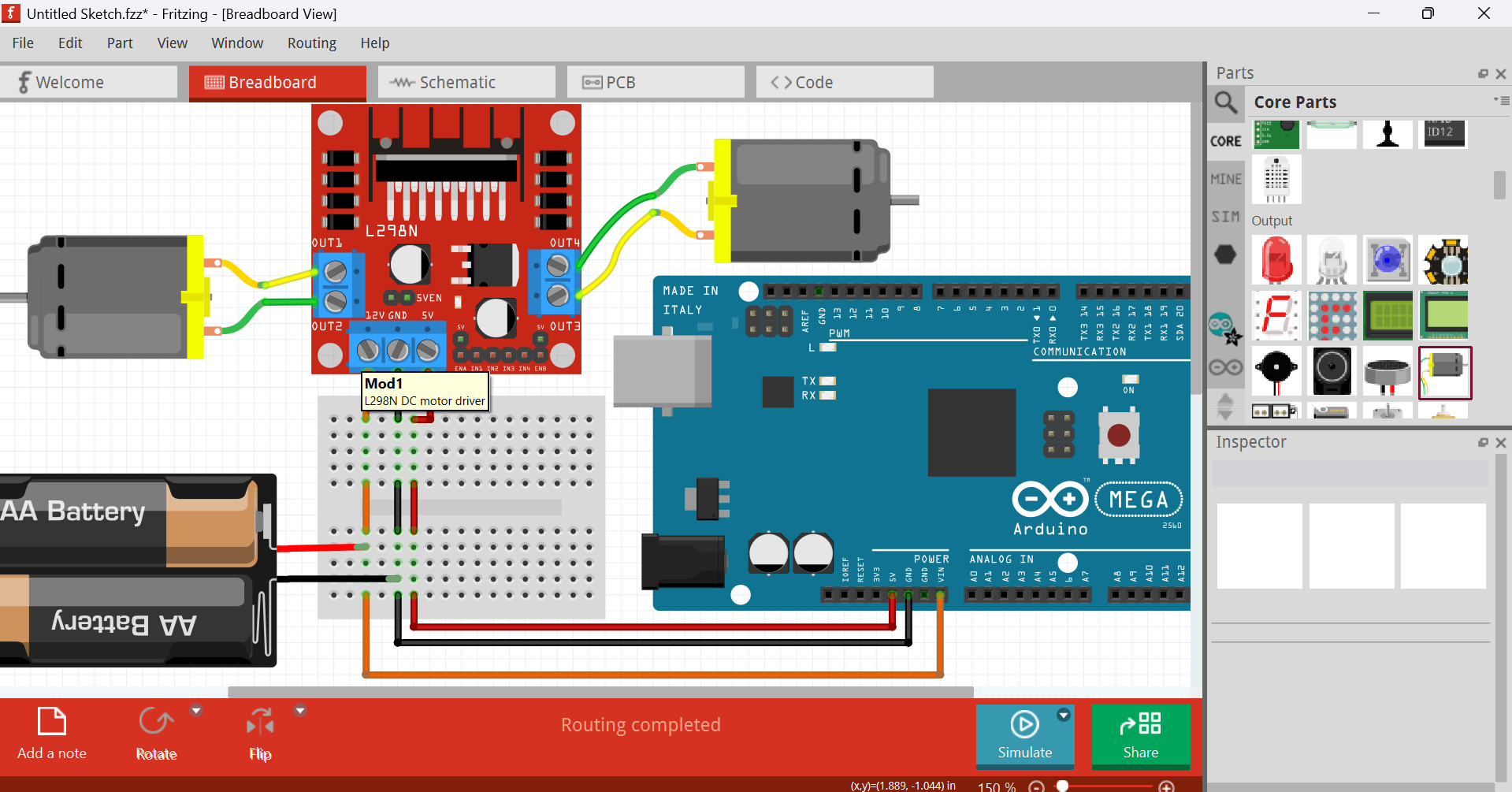
- Replace the arduino unos with an arduino mega 2560 (if the pins do not need ~PWM (pulse width modulation)
- Connect
12V → Arduino VIN
5V → Arduino 5V
GND to Arduino GND
To power the arduino, you can connect a 9V bat
You can also connect the NEMA-17 motor to an L293D

@Grandninga Like I said please attatch the .fzz file.
So far here is my circuit
robot_car_RAPTOR7762.fzz (79.8 KB)
And tell us what you need help with as well.
Peter
He/She needs help in powering the Arduino (maybe other issues as well)
@Grandninga Please also used my
Hello everyone,
I’ve attached the file Final Wiring.fzz (160.4 KB)
For this project, I’m restricted to using only the components shown in the file. While I would have preferred to use an Arduino Mega, I’m limited to the Arduino Uno.
The project is a differential drive RC car designed for planting seeds. The stepper motor powers the seeding mechanism, and I still need to add a servo motor to control the ultrasonic sensor mounted at the front. This setup uses a master-slave configuration, where one Arduino acts as the master controller handling decision-making and communication, and the other acts as the slave, managing lower-level tasks such as controlling motors.
My main concern is finding a safe and efficient way to power the entire system. We’ve been provided with two 12V Li-ion batterie since I’ve already fried the whole system before.
One with a capacity of 4800mAh
The other with 3000mAh
Both batteries are 3S1P and include a built-in BMS.
Additionally, since we are graded on having a complete and safe electrical design, the final wiring must include necessary components like capacitors, resistors, emergency stop button, and any other required elements for protection, filtering, and overall system stability—not just the core modules.
Any suggestions or advice would be greatly appreciated. Thanks in advance!
My first suggestion would be route schematic. Doing that will indicate errors in the breadboard view (which are easy to make.) Drag the components in to a reasonable placement (one that makes the routing easiest then click on a trace to make it a trace then drag it in to position. If you see unexpected connections you need to check (and likely correct!) breadboard to fix them. Fritzing version 1.0.4 tells me that you have 2 out of date components that it wants to upgrade, if you are using an older Fritzing version that may not be an issue though. If the motors aren’t 12V you will probably need a buck switching regulator with sufficient current capacity to reduce the battery voltage to the correct level.
This connection is likely wrong:
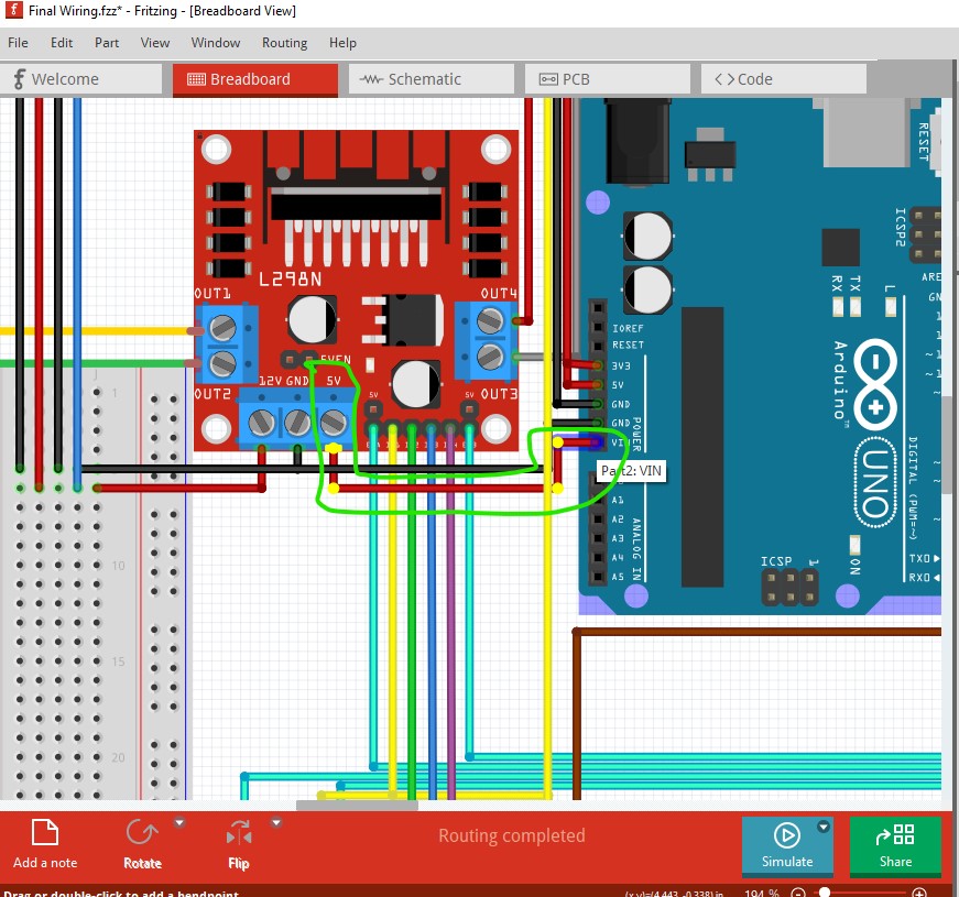
VIN needs to be 7 to 12V to power the Arduino and likely needs to come from one of the batteries (assuming the two are not being wired in parallel.) Using one battery (likely the higher amp hour one) for the motors and the other for the electronics would likely be a good choice as the motors tend to generate electrical noise which may affect the electronics. I expect the 5V terminal on the motor driver is from an internal 5V regulator from 12V which you likely don’t want to use for efficiency reasons (linear regulators are very inefficient!) Note if you left click on a connection (as I did on VIN) that will light all connections on that net yellow which is useful for finding missing connections (they can appear connected but not be connected for various reasons.) There are LIPO batteries available in core parts to represent the batteries (they will show as 3.7V though.) The emergency stop switch likely wants to disconnect both batteries from the circuit (so possibly a double pole switch, one half for each battery.)
Peter