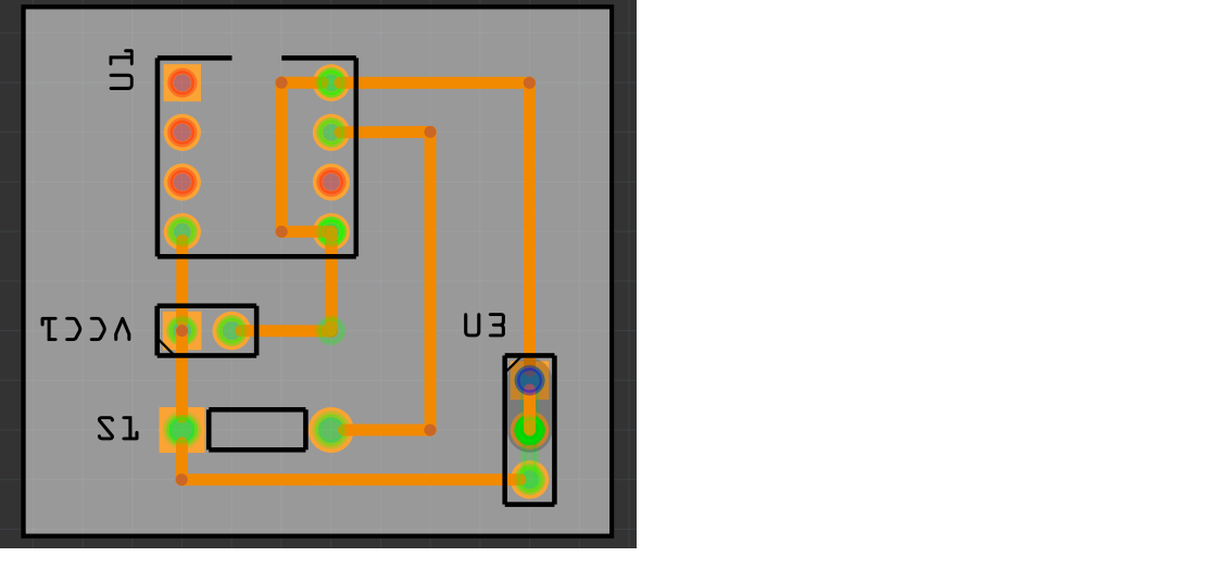
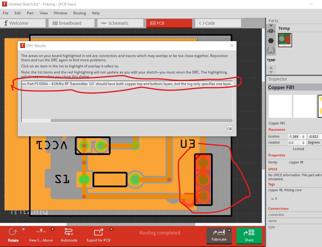
i feel like there is something wrong with this PCB wiring. i don’t know what the problem is, i tried checking the DRC and it says antenna fs1000a need copper on both top and bottom layer, also the wiring says that VCC and data should be connected.
Welcome aboard! First thank you for including the .fzz file, most people just post an image which is essentially useless for doing anything useful with. There are indeed problems but they likely aren’t yours. The FS1000A part is wrong. I obviously found it and checked that it loaded, but didn’t test further. I will post a corrected version in a bit.(probably in the original post though.) Here are a coupe of indications that there is a problem: DRC is the first one as you note. It is say the part is misconfigured as it only has one copper layer but is a through hole part which requires two layers. That is a fault in the part rather than your sketch.
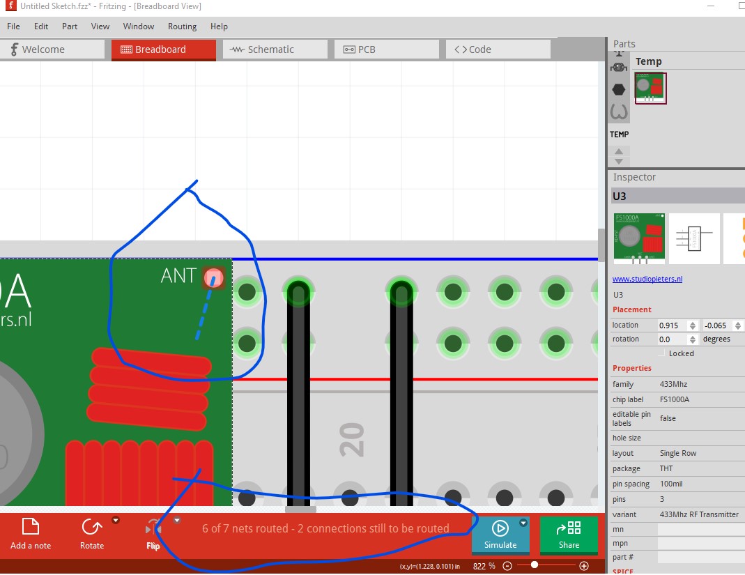
There are problems (some likely from the part) in the other two views as well. In breadboard we see that there are unrouted connections. You should always insure that the message at the bottom of the screen says “routing completed”, that doesn’t guarantee correctness, but lack of it indicates an error as in this case. The rats nest line indicates there is a connection in another view that isn’t routed here.
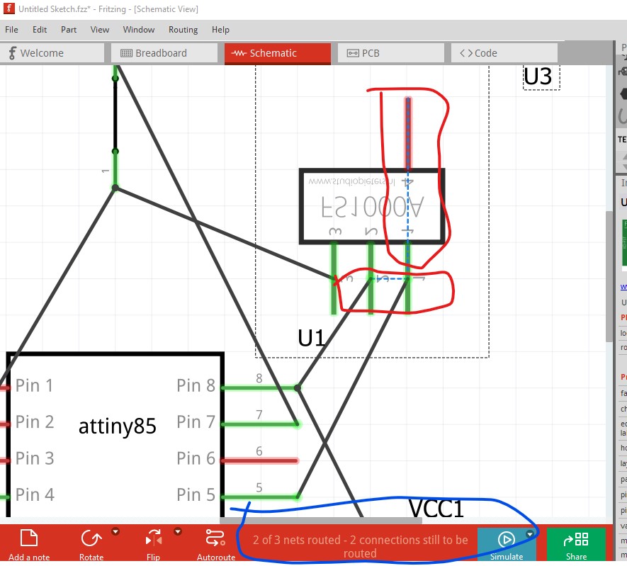
The rats nest lines indicate there are connections in another view (either breadboard or pcb) that are not correctly routed here. However most of the problem appears to be with the part. FritzingCheckPart.py flags this rather long list of problems with the part. As noted I will correct them and post a corrected part in a while.
OK I just posted fixed up versions of both parts in their original post here:
download both new parts and replace the transmitter in your sketch with the new part and things should work better. If you run in to problems, feel free to post (preferably with the sketch!) and I will have a look.