Hello, I created a new part by editing a new part and saving my edit as a new part. I changed the pin names under Connectors but when I go to the Schematic view the pins are still labaled 1 through 18. There doesn’t seen to be any other way to change the pin names that I can see. This is version 0.9.9.
Correct, there isn’t. To change the labels in schematic in parts editor you would need to edit the schematic svg with an svg editor such as Inkscape and then import the modified schematic svg using the parts editor.
Peter
Okay, I thought that might be the case. Thank you!
hI vanepp,
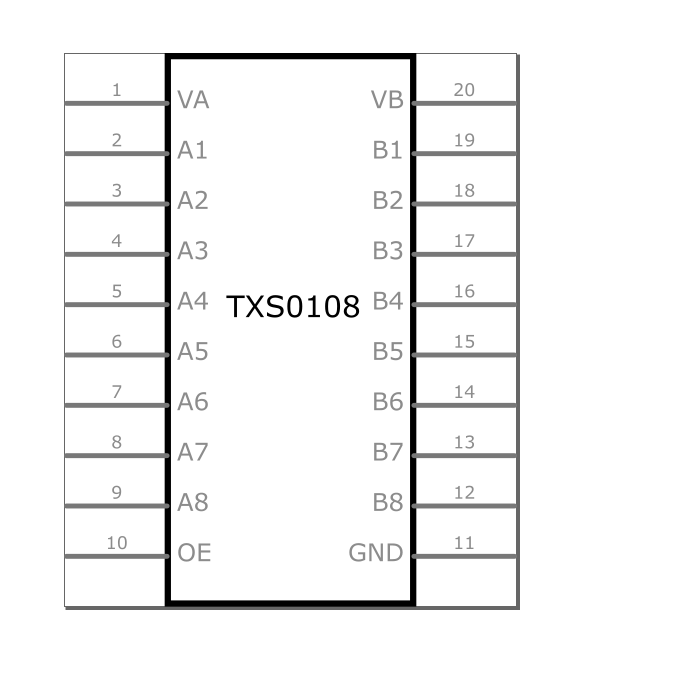
i tried to modify the schematic image of a TXS0108 starting from a model found here. Goal was change the pin and align them with “functional name”. I used Inkscape and following is the result. First image is from Inkscape, second is the result in Fritzing. What’s wrong ?
Thanks
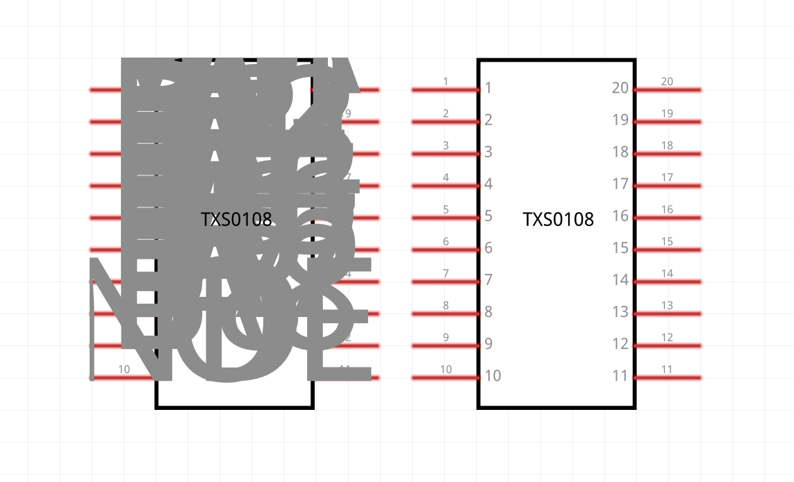
Likely he font-size in the svg has units of px which Fritzing objects to. You either need to run the part through FritzingCheckPart.py (which among other things will remove the px from font-size) or edit the svg with a text editor and remove the px from the font-size elements (I usually just do a global replace of “px” with “”.)
Peter
Hi,
SVG file ? I found PX like <p style=" margin-top:0px … > in the FZP file.
Thanks,
Ok, i found your tutorial for part creation so i probably only have to read a little and i will found how to ,
Thanks
If you export the part as a .fzpz file (right click on the part in the parts bin and select export part) then unzip the fzpz file you will get a .fzp file and 4 svg files. You need to edit the one called svg.schematic.filename.schematic.svg to remove the px from the font size. Or you can feed the .fzpz file to FritzingCheckPart.py (available here)
and that will remove the px from the font size (as well as check for other errors.) This is indeed in the tutorial series as well.
Peter
No way Peter, try to install the tools but i’m not skilled on that stuff and following the guide im not able to run the scripts.
I’d like to try a manual way, i read about inkscape configuration and apply it (in reality not sure if i have to apply that config after open the image i want to modify, but think yes because after opening the doc preferences changes), but can’t understand what to do for:
Opening that file with a text editor there aren’t “px” terms to substitute with “”. What you mean exactly ?
Steps are
1)upload device in fritzing
2)open the editor device
3)modify the image with inkscape
4)upload the modified image (in the right tab eg schematic)
5)save and back to fritzing dashboard.
In between (or following) i need to modify the schematic.svg with text editor (in the way i still not understand).
That’s it?
Sorry for my low level questions and thanks for support,
EDIT: Do you mean deleting from the text 20 [font-size=“34.7222”>20</text>] e leave blank ?
For all [font-size] attributes i found in the file .svg ?
Matteo
After you have saved the svg in Inkscape, you then need to edit the file in a text editor (I usually use vi in cygwin, which is what I have used here)
you should see something that looks like this:
<text
   x="305.0"
   y="205.0"
   font-family="Droid Sans"
   font-size="60px"
   fill="#000000"
   id="label"
   text-anchor="middle">LM2731</text>
<text
Of interest is the line ‘font-size=“60px”’, that needs to change to ‘font-size=“60”’ like this:
<text
   x="305.0"
   y="205.0"
   font-family="Droid Sans"
   font-size="60"
   fill="#000000"
   id="label"
   text-anchor="middle">LM2731</text>
I do that by globally replacing px with nothing to remove the px. You need to figure out how to do this in what ever text editor you use. It can be done manually by deleting all the px, but that is very error prone and missing one will cause problems so you are better off to figure out how to do it automatically for the entire file.
Peter