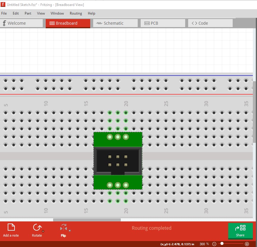
So, breadboard view: I have a 2 x 6 shrouded male connector and I can’t for the life of me figure out how to incorporate it on the breadboard. One way, both rows of pins are in parallel, the other way each column of pins is in parallel. How do I proceed? Do I just skip it and go straight to PCB view?
Not on the breadboard as the pins will all short. You would need an adapter plate that spaced the connector 0.3in apart so it fits across the rows on the center or to run wires from the connector like this:
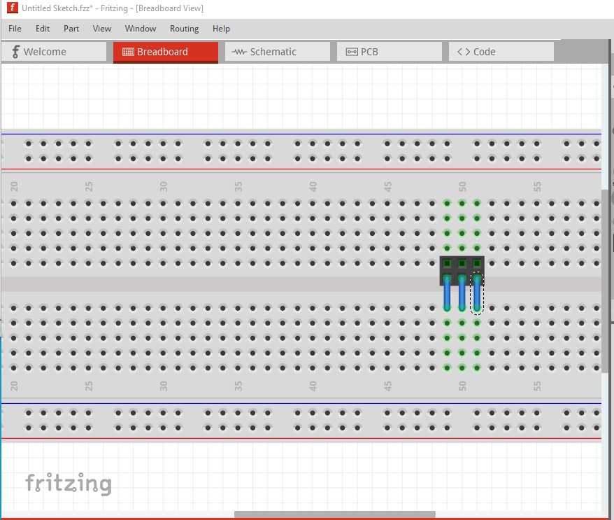
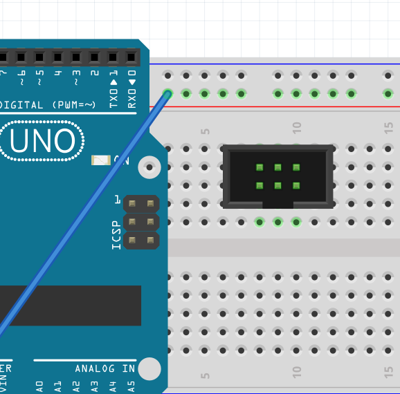
The header here is simulated by 2 3 pin headers as I don’t have a shrouded breadboard connector handy. The top 3 connectors connect to the top 3 rows, the wires connect the bottom 3 to the bottom rows of connectors. The same thing can be done with a custom part that has an adapter board that does the same thing (although I don’t know of such a part at present it is easy enough to make.) As shown in your diagram the connectors short together on the breadboard.
Peter
Thank you. Since that would result in a PCB feature I don’t want, should I just skip the breadboard?
You can do that, but I’m not sure what pcb feature the method I used (the shrouded connector to the breadboard on one side with wires to the other side of the breadboard) would cause. Neither the wires nor the breadboard will reflect in pcb, you will only get the pads for the connector with rats nest lines for the appropriate connections. The advantage is that you have the connections in breadboard which I find makes it easier to make sure the correct connections appear in pcb (and in schematic!) I have often identified wiring errors by seeing unexpected rats nest lines in schematic or pcb. If you make a part for a custom adapter, breadboard can be different than pcb leaving pcb as it is now, but that requires being able to make a custom part which isn’t that simple.
Peter
I created a breadboard adapter part for a similiar situation. I did not figure out how to keep FritzingCheckPart happy with the result. It complains about things that don’t really exist that did not figure out to make totally not exist. This is intended as a breadboard view only part, and as an extension of a breadboard.
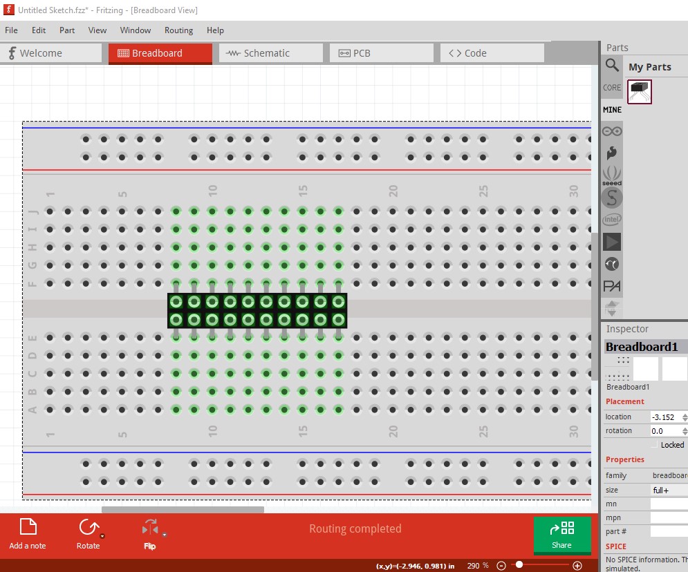
This is a ‘carrier’ part that connects to a breadboard like a standard DIP, then provides connectors as 2 rows of side by side pins as in your shrouded connector. Position this on a breadboard, then the connector on top of that.
2-by-10-header2dip.fzpz (3.7 KB)
![]()
While your part appears to work, I’m not sure how (and FritzingCheckPart appears to be complaining correctly!)
attached to breadboard it appears to connect correctly. However in the fzp file connector0 looks like this:
<connector id="connector0" type="male" name="pin 1">
   <description>header dip pin</description>
   <views>
     <breadboardView>
       <p layer="breadboard" svgId="connector0pin"/>
     </breadboardView>
     <schematicView>
       <p layer="breadboard" svgId="connector0pin"/>
      </schematicView>
     <pcbView>
       <p layer="breadboard" svgId="connector0pin"/>
     </pcbView>
   </views>
 </connector>
the breadboard svg however has no connector0pin that I can find and FritzingCheckPart correctly complains about that:
Error 18: File
‘part.2-by-10-header2dip.fzp.bak’
Connector connector0pin is in the fzp file but not the svg file. (typo?)
svg svg.breadboard.2-by-10-header2dip.svg.bak
Error 18: File
‘part.2-by-10-header2dip.fzp.bak’
Connector connector0socket is in the fzp file but not the svg file. (typo?)
svg svg.breadboard.2-by-10-header2dip.svg.bak
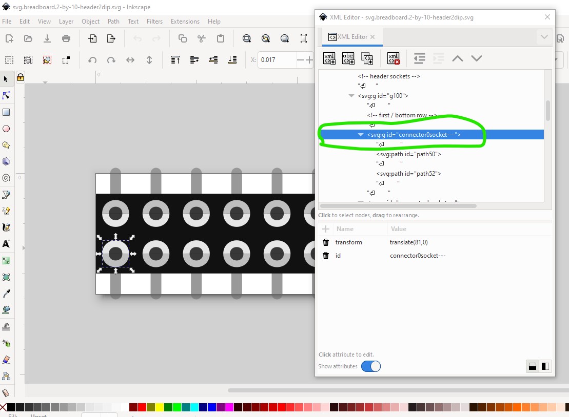
connector0socket also doesn’t exist (directly) in the svg it is
<connector id="socket0" type="female" name="socket 1">
  <description>header socket</description>
  <views>
    <breadboardView>
      <p layer="breadboard" svgId="connector0socket"/>
    </breadboardView>
    <schematicView>
      <p layer="breadboard" svgId="connector0socket"/>
    </schematicView>
    <pcbView>
      <p layer="breadboard" svgId="connector0socket"/>
    </pcbView>
  </views>
</connector>
In the svg it is connector0socket— (which is a group which I think CheckPart will also complain about!) which doesn’t match the definition in the fzp but seems to work somehow anyway (possibly breadboard magic?)
I expect it is possible to correct all these (although since this seems to work somehow that may not be worth doing!) Because this set up to be a breadboard I don’t think it will do what the original poster wants, which as I understand it, is to have the adapter plate in breadboard have your spacing (which is possible to do without being a breadboard) while having pcb view be a standard 0.2in pitch header without the extra 0.1in width needed in breadboard to make it fit in the breadboard.
Peter
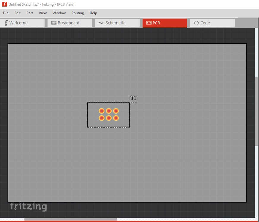
This should do what you want (assuming I have understood what you want correctly!) In breadboard it is 0.4in wide in pcb it is 0.2in wide (and 0.1in pitch)
2x3-shrouded-header.fzpz (5.6 KB)
Peter
My part, being a breadboard, does not need to exist on PCB view. The part that is plugged into is all that pcb view needs. All of the connections are passed through. At least that is my memory from when I did it.