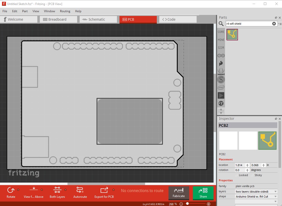
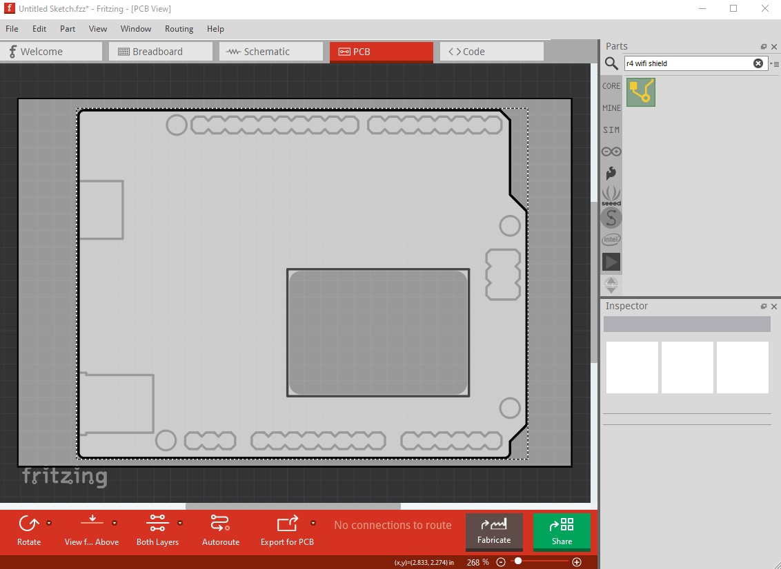
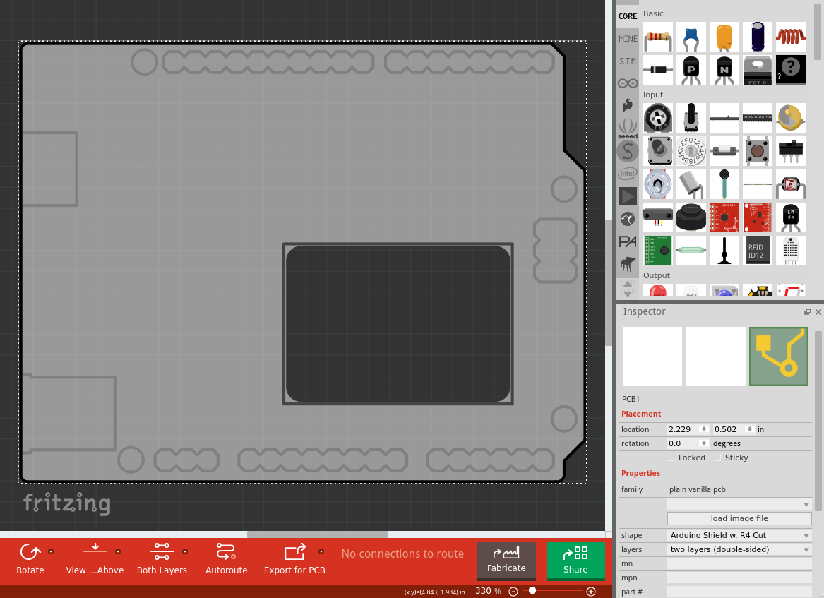
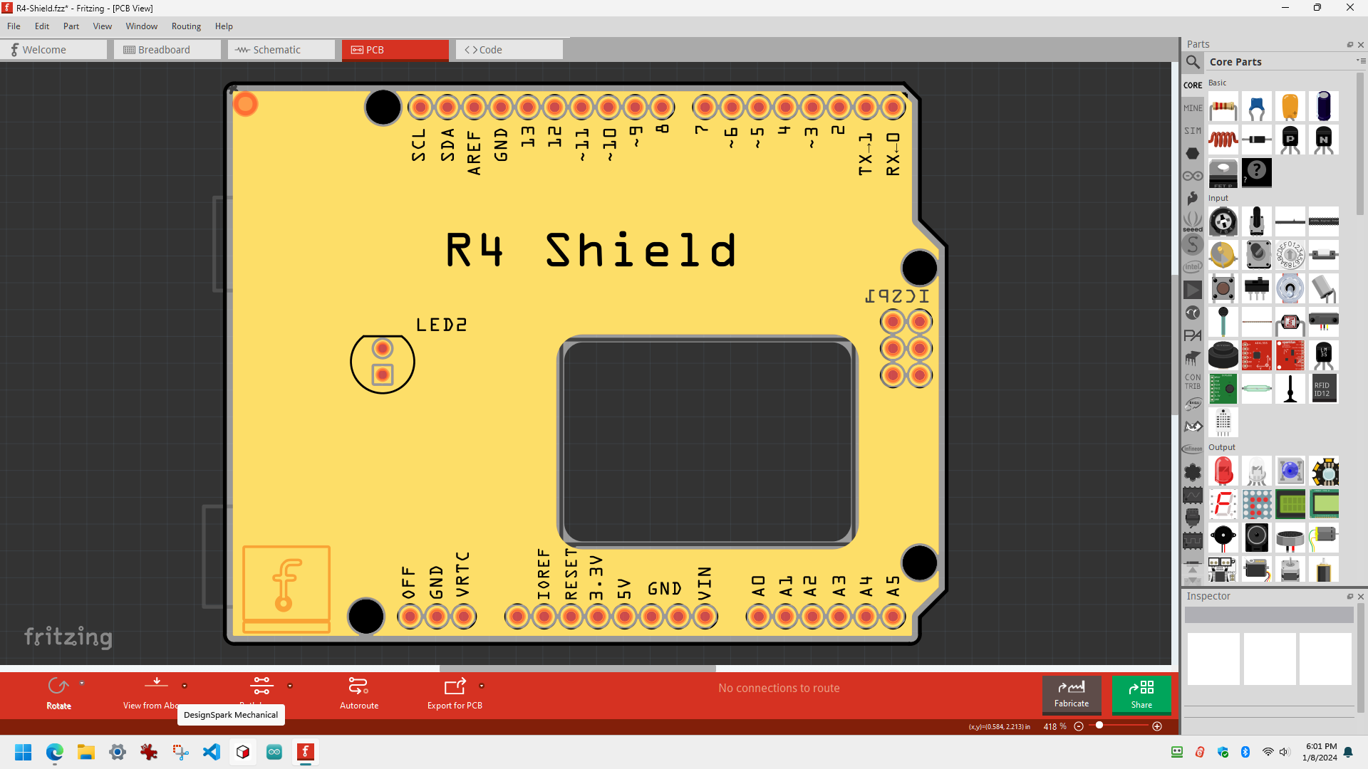
There is supposed to be an Arduino sized board with a cutout for the display on the R4 WIFI Board.
I found it in the parts, but all I see is this.
There are no markings at all.
Am I missing something?
There is supposed to be an Arduino sized board with a cutout for the display on the R4 WIFI Board.
I found it in the parts, but all I see is this.
There are no markings at all.
Am I missing something?
While I’m not certain, it looks like this is broken to me.
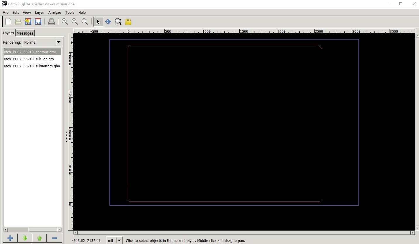
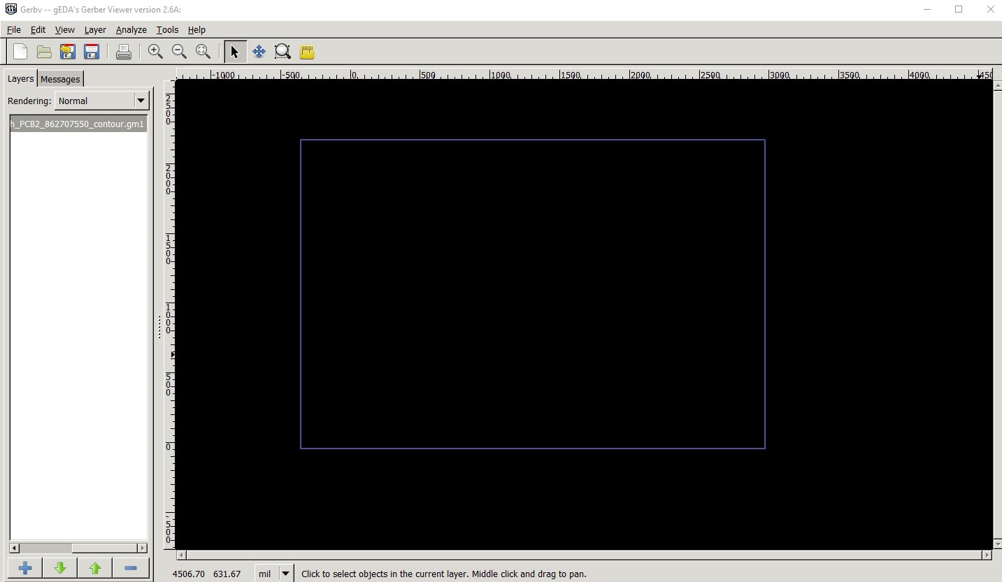
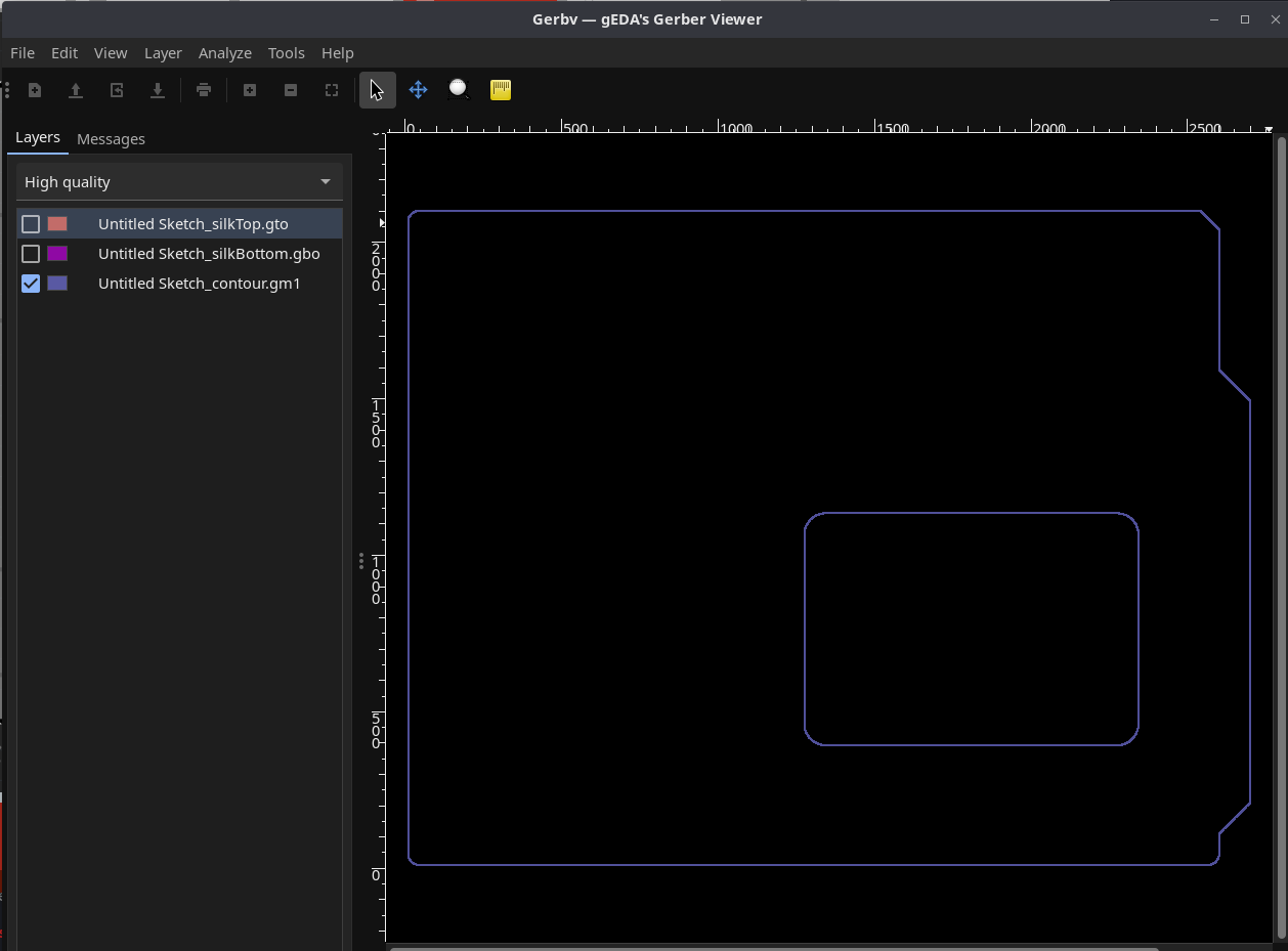
this looks to be a template outline that you use to make a board. I don’t think (although I may be wrong!) that you can make a slot directly from pcb view, you normally would need to make a custom svg (which is not at all easy!) and load it via load image file to create the slot. Exporting this as gerbers does not produce the slot (and in fact the outline appears to be broken as well!) This is the gerber output of the above displayed in gerbv
the outer purple rectangle is the contour.gm1 file that would normally cut the slot for the R4 if it was working (which it doesn’t appear to be.) The usual thing with these templates is that you drag in to your sketch the pads that you want (and presumably create a slot capable svg that you load via load image file like this
although as noted you need the svg file that defines the slot which doesn’t appear to be here. Perhaps someone else will know more, this is the first time I have seen this particular template.
Peter
Yes, looks broken to me too. Here is what they show on the Frizing website:
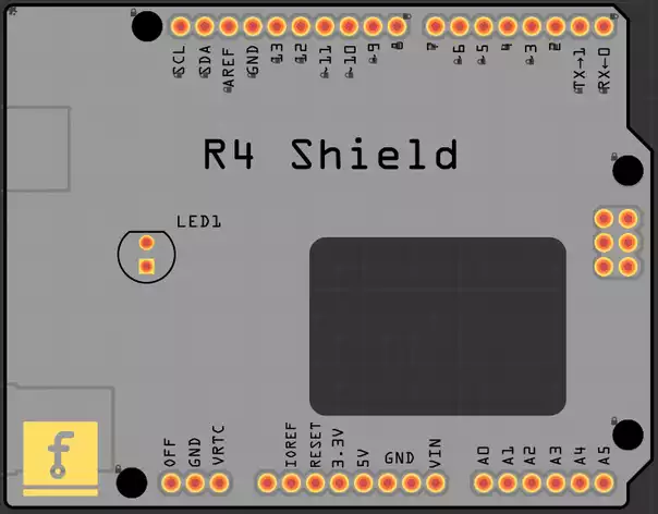
That could be the result of using the template to make a sketch. I assume they mean you to add the slot svg because as I said I’m not aware of a way to make that from a part. It looks like they have dragged in holes for the mounting holes and pads for the various connectors. Given the difficulty of making that svg I’d sort of expect one to be available somewhere but I don’t know where.
Peter
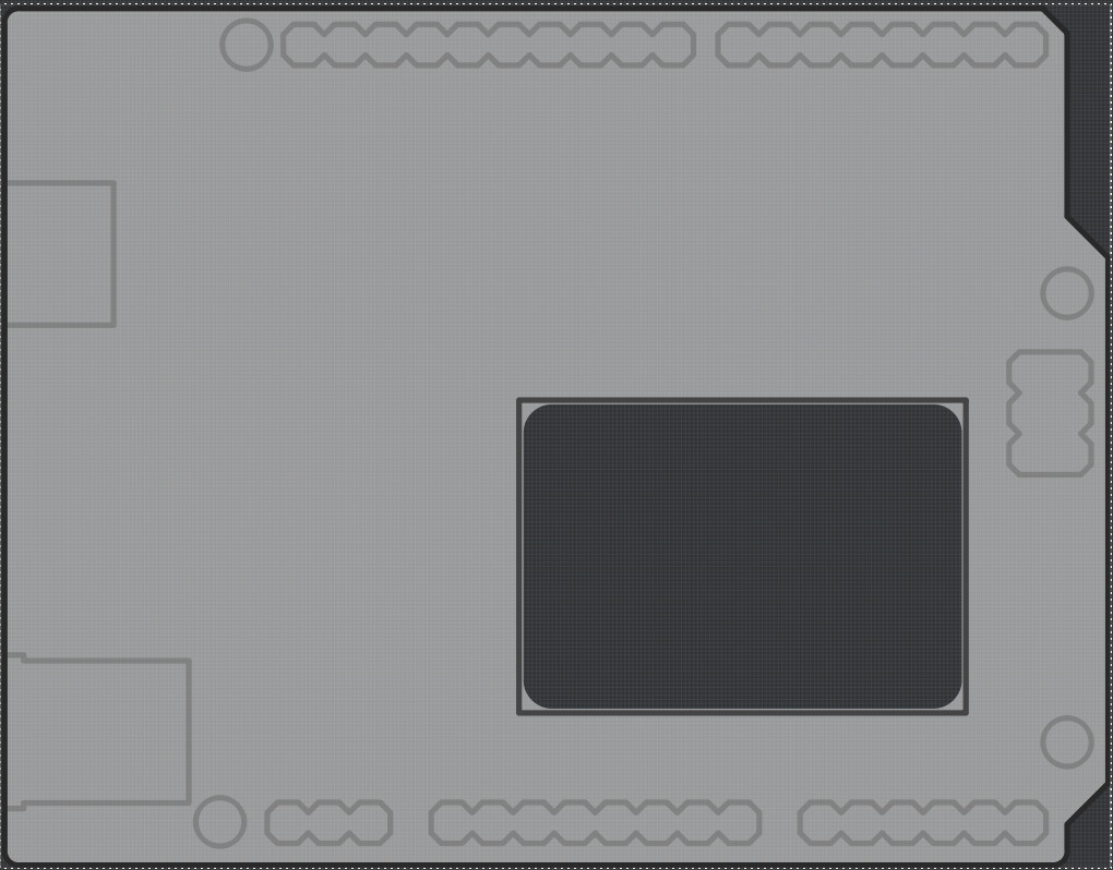
It is not broken, it is just the plain board.
Please open the File → Examples → Shields to get what we display on the website.
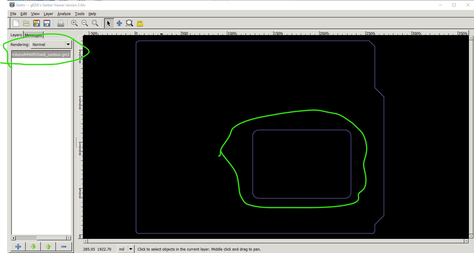
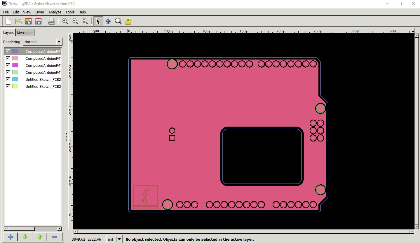
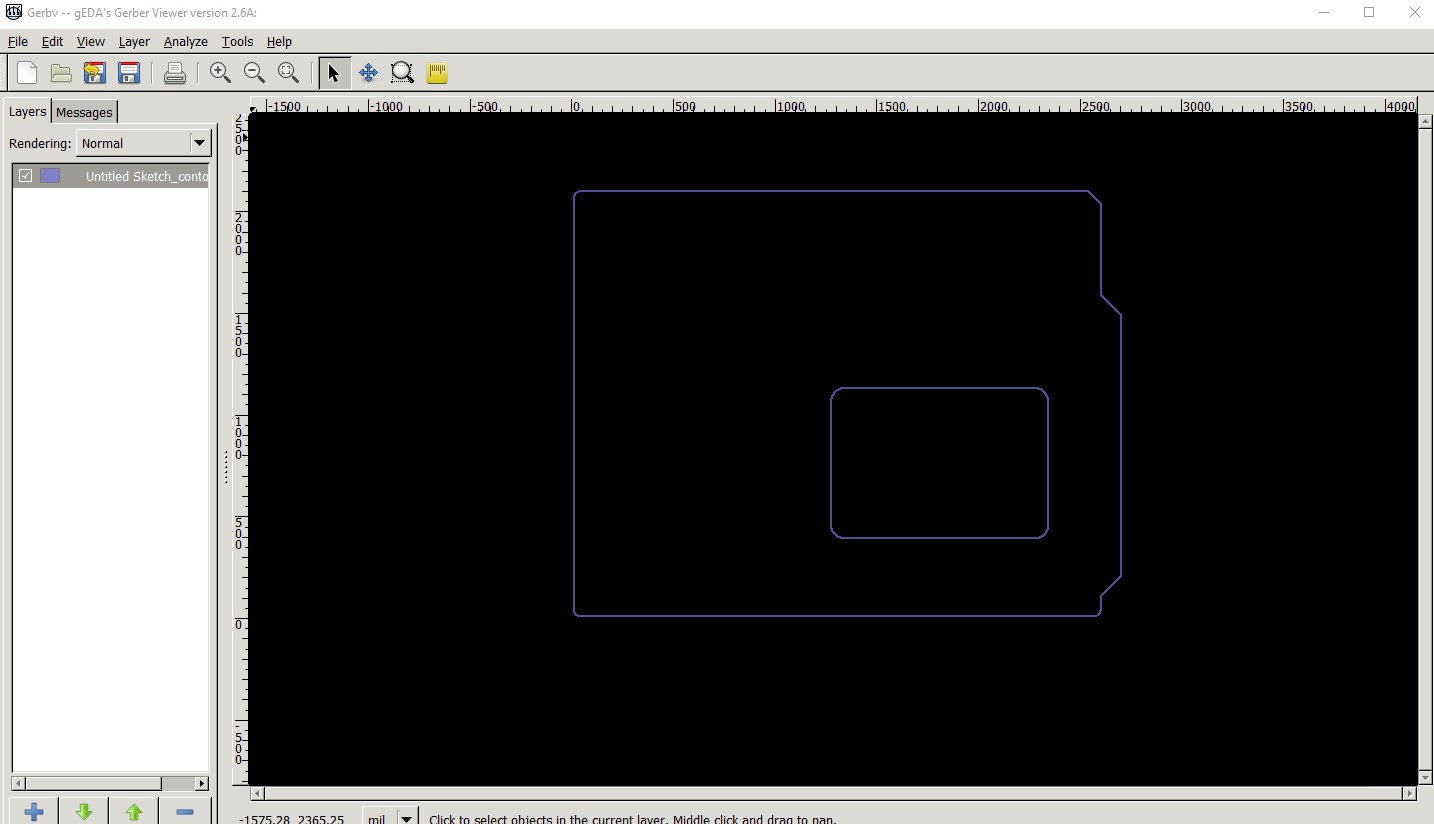
Interesting! The .fzz in examples appears to work correctly (where as the template does not as it doesn’t render either the outline of the hole in the gerbers!) This is the output of the example file exported as gerber and displayed with gerbv (contour.gm1 only here)
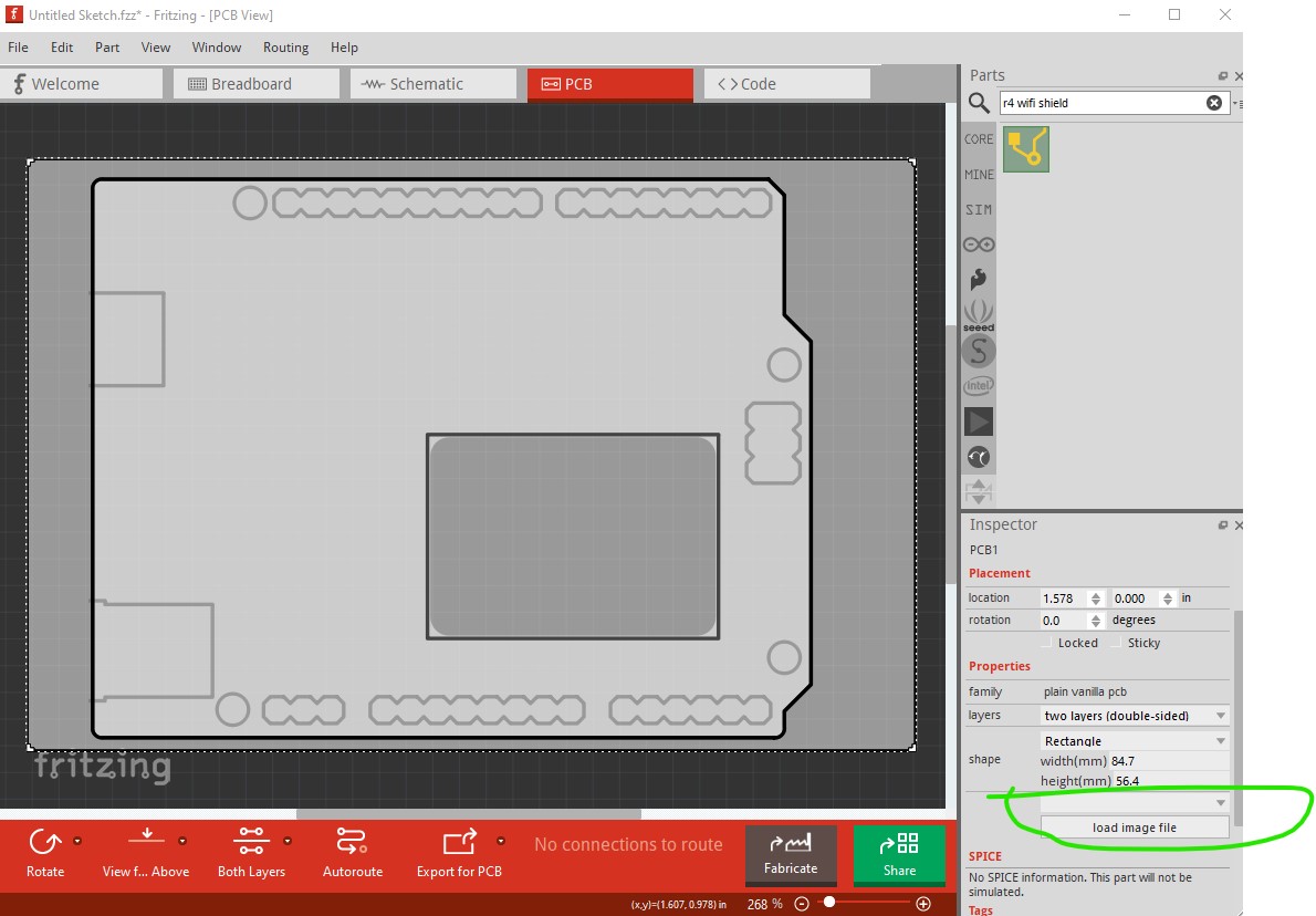
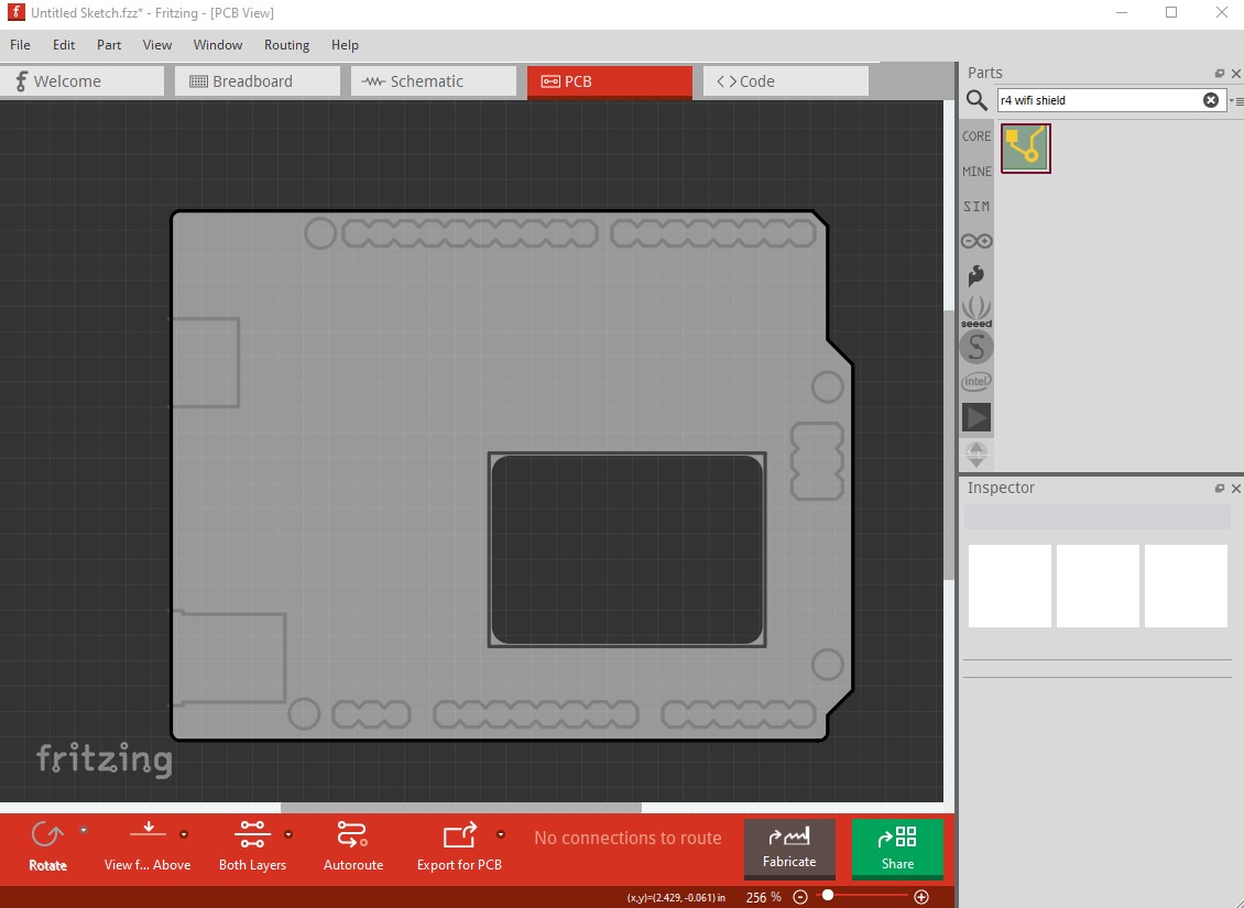
This is the template part in Fritzing
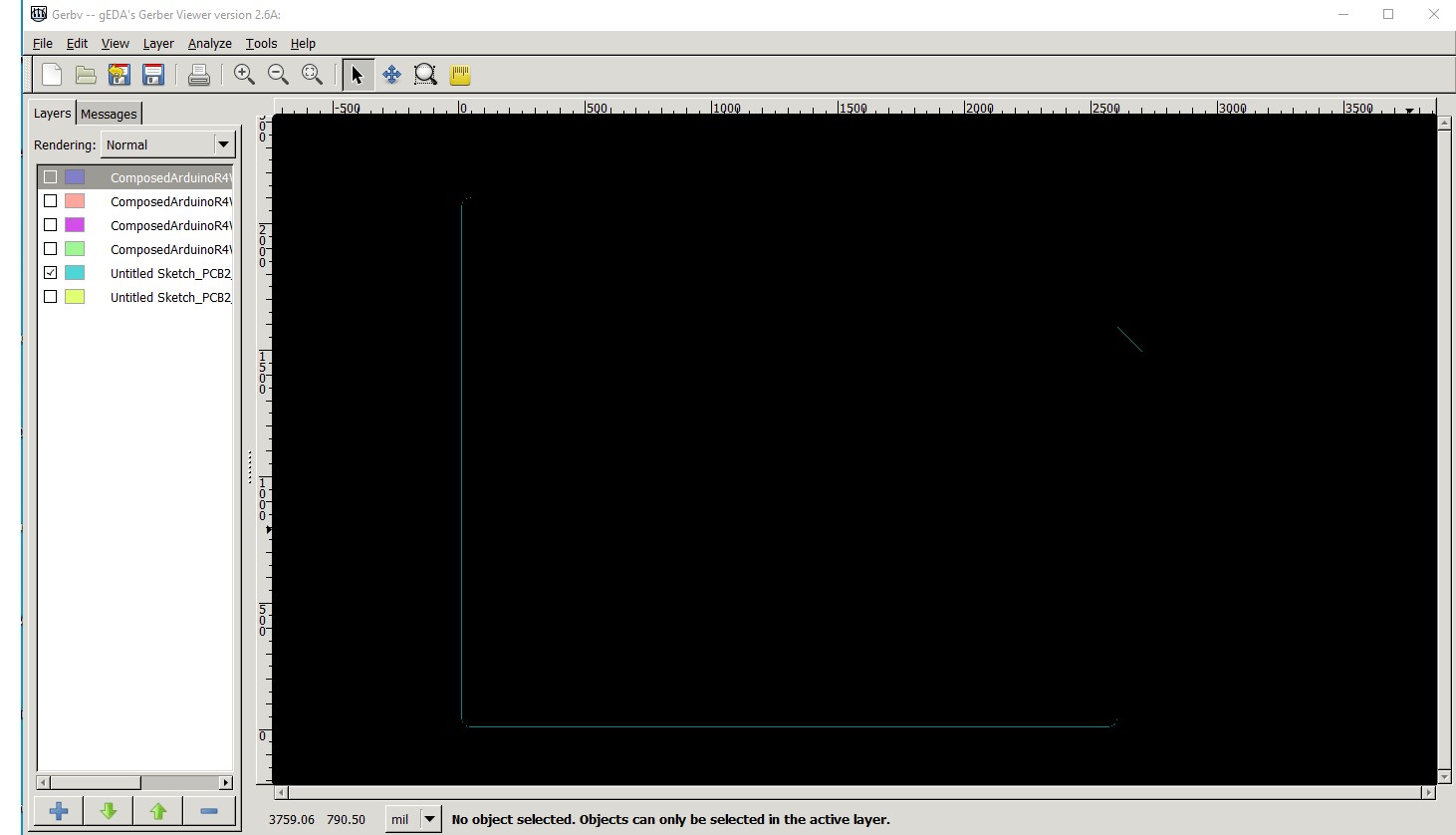
but the contour.gm1 file has neither the outline nor the LED slot. Switching to the example output again, the silktop there is not rendering correctly. Neither the outline nor the text is appearing on the silkscreen (and I though we had fixed all the rendering bugs in gerber output!)
with all layers enabled the contour.gm1 is working correctly but silktop doesn’t appear to be.
I assume you achieved the slot in the .fzz file by loading an outline.svg file in to the sketch before creating the .fzz? In such a case it would be a good bet to provide a copy of the outline.svg fine (which is recoverable from the .fzz file if you know how to do it!) @PickyBiker, the correct advise (if I had known that the example existed) would have been to point you at that which would do what you wanted without requiring you to implement the outline.svg for the slot!
Peter
@vanepp You have loaded two boards here, only the selected one should be exported

If you only use the raw part, you get a correct contour file.
The outline file is exported as a contour, with the outline itself, and the cutout in reverse orientation, so the CNC machine will detect it as cutout.
I have tested that this cutout strategt works quite some time ago, with Fritzing 0.9.10. And of course this might also depend on the Fab.
@vanepp Ah, I see what you meant. The silkscreen rectangle around the cutout is not visible, only within the example fzz.
The other lines around the connectors, the holes and the plugs are only decorative, they are not part of the silkscreen.
Learned something new yet again! You are correct I dragged the part in to an existing sketch which has a pcb. When I delete the pcb and leave only your part it works as you say and produces a hole from a part. I will need to look at the svg for this part and figure out how to do this …
and what looks to be correct gerber output
This should help with adding slots to parts, I didn’t think this was possible!
Peter
Don´t load the SVG as image file, just select it from the available shapes.

Does it have to be in the list of available shapes for this to work (i.e. I can’t create a pcb svg with a cutout path that will do this?)
Peter
It should work with any part.
I know how to do electronics, but I am not an expert on Fritzing so, I hope that the outcome of this discussion is a step-by-step process for someone like me to be able to make one of these R4 Shields with our own electronics design added.
@PickyBiker Please open the File → Examples → Shields to get what we display on the website.
I did that but the item of interest is surrounded by large yellow boxes. How do I get rid of those?
I turned off the Notes Layer and I no longer see them.
Now when I click view->Fit in Window, it doesn’t expand properly. I suspect the notes layer is still there, it’s just not visible.
So how do I remove the notes layer?
Did you see only yellow boxes, or were there actual notes inside the boxes?
Delete operations in Fritzing work mostly like in any other editor.
Here is a copy of the examples shield.fzz file with the copper fill and notes deleted.
ComposedArduinoR4WifiShield.fzz (6.8 KB)
downloading this .fzz file and double clicking on it should give you a sketch that you can modify to add your components and traces to make a new .fzz that you can then create a shield from.
Peter
I saw the yellow boxes with text inside.
I just deleted the note boxes!
I was originally clicking in the box and that deletes text characters. I clicked on the very bottom of the box and hit delete. That did delete the box!
I now have everything I need to start putting my electronics on the shield.
Thank you both for the help in getting this to work.
Here is my result: