How to route out connections from the edge side of the RPi GPIO?

I am trying to make a raspberry pi add-on board, and I was wondering how I could get access to connections on the RPi’s GPIO that are next to the edge of the board?

I set the autorouter to do it, and it successfully routed 2 out of 3 of the connections I had created in schematic view, but when I ran DRC it said they were too close to the edge of the board.

This a picture of the PCB with the DRC window open:

Any help much appreciated!!

Generally it’s the method of production that dictates if it’s too close to the edge. Production houses are accurate and can run close, home DIY etching depends on your skill.

The DRC makes you aware of problems, but it’s up to you to decide if it’s ok to ignore.

Other hints
Generally nobody uses 90º bends in their traces anymore, they are all 45º elbows now. It can cause resonant frequencies.
Generally nobody uses auto route because it’s not smart enough - it’s a legacy from the 80s when everything was vertical in one layer and horizontal in the other -.

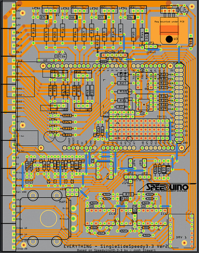
This is all hand routed

After you draw the trace, in the Inspector window, next to width, click on the drop down window and select 8 or 12 mill. that will go between the pins. 8 or 12 mill is fine of data. Power should be a little heaver depending on the current. Also, in the main menu under View, set grid to 0.05" and make sure your pins line up with the grid. Draw a short 45 from the connector pin then virtually between the 2 connector pins. Sometimes the DRC will say you are too close to the pins… you are normally OK and can ignore it.

Never use auto rout and don’t make 90" corners, they should be 45s. Draw all traces on 90 and 45 deg. with few minor exceptions. Don’t draw ground traces… use the Ground Fill instead.