Hello, I’m a new Fritzing user… just did some tests. It looks interesting although I don’t like the American symbols.
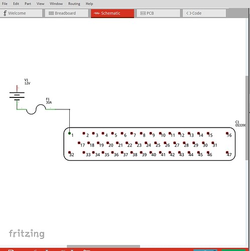
But how can I produce a decent clean schematic to export, not with those stupid green design lines, but just black lines as it should be?
I hope it is possible, since the default exports look like some patchwork…
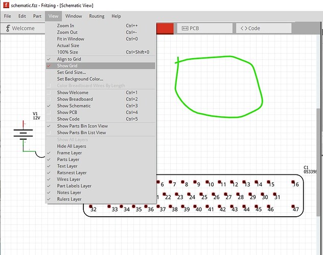
A screen image of what you are talking about would be useful. If you are referring to the grid lines (circled in green here)
They can be removed by clicking on View->Show grid
which toggles them on and off.
Peter
I want the green lines gone! Even if I set that color to black, you still see those peaces of wire highlighted, which looks like rubbish. It’s not useable in a publication!
There should be a way to NOT show those design things in a “finished product”, I hope!
Since I have no idea what green lines you are talking about, I have no answer. As noted a screen shot of what you are looking at or upload the sketch file you are dealing with and point out what you are objecting to may get you a solution (upload is 7th icon from the left in the reply menu and the .fzz file is the sketch.)
Peter
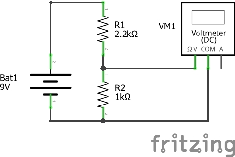
This is the result of exporting a schematic as JPG, ugly as hell… Not usable for any publication.
Fritzing is about combining the breadboard/schematic and pcb view. So it shows when connections are completed in green on all three views. Those change together.
For doing pure schematics, fritzing is not great. It has a number of default symbols which are a pita (potentiometers and switches).
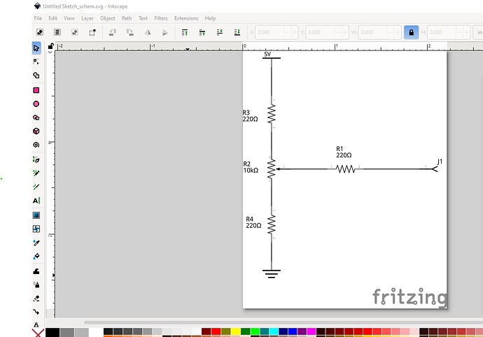
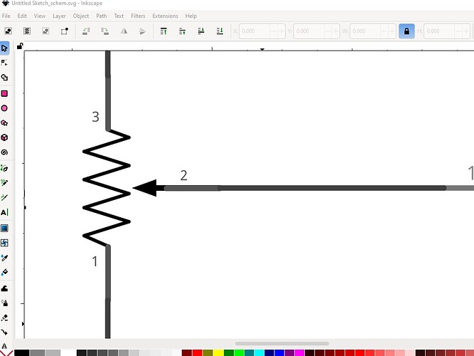
If you do export an svg, you can just open it and select all elements of a color and swap them to black. But that’s also a pita.
EDIT:
A crappy schematic, edited with with Extension-> Color → replace color in Inkscape. it’s a pita.
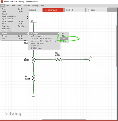
That image is just Export / As image / SVG
Note that the potentiometer symbols were updated a few versions ago (thanks to Peter). If you do not want to upgrade Fritzing, you could download the latest version of the part repository.
What Fritzing version and OS are you using? On Fritzing 1.0.4 (the current version) on Win10 this doesn’t happen for me. Here I created a random schematic (with the current pot) then exported it as an svg:
the resulting svg doesn’t have the green connector lines you are showing
edit
here is the actual output svg so you can look at it in an svg editor (right click on the image and use save image as to download the svg)
Peter
Thanks for the feedback. A while ago we had a discussion about “fixing” the interactive elements (green lines and red lines) in the SVG, so that the SVG export is aligned with the other exports. I took a note on the side for not doing this, but instead adding an option to the raster graphics export dialog:
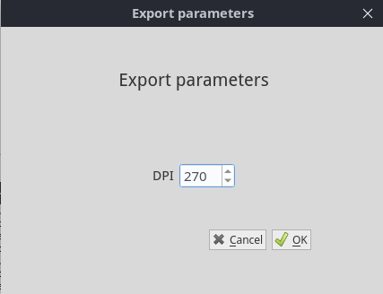
How is this export working? The standard file->export->as image->svg doesn’t appear to create the green lines (at least for me.) Is there another way to export a schematic? I’ve also never seen the export dialog anywhere.
Peter
The export dialog is for raster graphics like PNG and JPG. It should be shown always when exporting to these formats.
The SVG export does not highlight interactive elements like the green and red connectors. But we had (maybe still have?) a bug report, that suggested to highlight them, even for the SVG. I had a hard time to argue that this is intentional, not a bug.
I think my reasoning was: Vectors graphics are more likely used for print (not interactive), while raster graphics are more common for screens, where the similarity with Fritzings interactive rendering might be preferred.
I would agree that it should be as it appears to be. The connector markings (at least in my view) shouldn’t be exported to the svg.
Peter
The SVG is better than the PNG, but still I have to replace all the greys with black.
Only one line of code in the software has to be changed to do that automatically. Also to remove the green highlighting in the PNG, it’s just a matter of 1 line of code: set the “visible” property from true to false before the export. This little change would mean a great improvement!
Then make an enhancement request on github. Maybe it will get done, depending on what else it may effect. The code base is very complex and things that appear simple often are not (or have undesirable side effects.)
Peter
I personally think that we can remove them or make them optional. What I really don’t like it that the connectors have three colours: red, green or grey depending on their connection. And this is confusing when reading schematics.
In any case, orcad also has colourful schematics:
https://images.app.goo.gl/JYBS3JTLVJSbMhYu7
Note that all connectors are the same colour and different from the wire colours.
Hmm. That export is from version 1.0.3. Maybe it’s the part that’s an issue? I can’t easily update all my sketches ( I have 9 actively devloped sketches using those parts). I’ll update to version 1.0.4 anyway, but doubt that will help.
EDIT: I just looked and it seems that the parts I’m using are referred to as ‘obsolete’. That’s just great. Sigh.
Damn it. This is not good. The new ‘Small’ pot variant differs in footprint. The original was not especially accurate (for the outline) for any pot (Alpha/Alps, RK097N, RV09, etc) that I use. I’m not really sure what to do about this. All the parts are now embedded in the app image so it’s not like I can easily update parts. EDIT: THIS is off topic. I’ll create a new topic.
