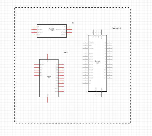
Is there a way to draw a dotted line in schematic? I have a section of the schematic that I want to surround with a dotted line to indicate that the section is optional and does not have to be used. I realize this would have ramifications for the breadboard and PCB layout, of course.
I’m not sure there is a way to draw a dotted line in schematic (although someone else may know a trick), you might look at the schematic frame (a drawing title box) which I think can have a box around it. That may work to isolate the circuitry on schematic. It can be found in the core parts bin Schematic view (5th from the left). That will create a title block (where you could indicate this is optional circuitry) and create a solid (I don’t think dashed is an option) line around the optional circuitry. As you say the parts will still show up in breadboard and pcb, but they would need to if you wanted to install the parts.
Thank you Peter. It seems odd that there isn’t a way to do this. Over the years I’ve designed many circuits that had optional sections where one could leave out parts that may not be needed. I can see where putting in the etch makes sense, as well as the breadboard.
I’m doing a design for a magazine article. I guess I could print it out, draw in the dotted line and then scan that. Perhaps there would be a way to “shade” an area with a light color?
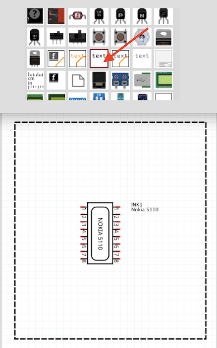
In the core parts under the schematic section you will find a text part. Drag it out and type in a series of dashes and spaces to make a line. Then copy that line four times and position them in a square around your optional section. You will have to rotate two of them to be vertical.
It would still be a nice feature to have in the software to be able to just draw a dotted line. Dotted lines are also used to show that two parts are connected, such as a potentiometer and an included switch on the back.
Another alternative to @sublimeartistry 's suggestion above would be to export the view(s) you need as an svg via file->export, then use a svg editor such as Inkscape to add the dotted lines. It is a little messy (you would need to redo the export and re edit the svg if you change the sketch) but it should work, but if it works for you , @sublimeartistry 's suggestion is better as it is in the sketch with no post processing required.