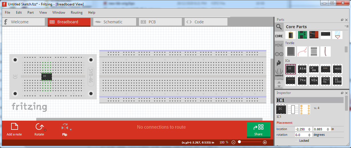
Because all the FRANZIS-Advent calendars and some other suites for beginners are using the SYB-46 board, I wanted to create it for fritzing.
But sadly I can not using it in fritzing itself.
I have copied the file SYB-46.svg in .\fritzing-parts\svg\core\breadboard
Additional I have in .\fritzing-parts\core\ made a copy of breadboard2.fzp and copied it to SYB-46.fzp.
I edited then the file by replacing <layers image="breadboard/breadboard2.svg">
to <layers image="breadboard/SYB-46.svg">
and changing module moduleId="Breadboard-RSR03MB102-ModuleID"
to module moduleId="Breadboard-SYB46-ModuleID"
Then I added in .\fritzing-parts\bins\core.fzb
behind
But sadly it don’t work.
After starting Fritzing, there comes then the error message
Das folgende Bauteil konnte nicht gefunden werden:
‘Breadboard-SYB46-ModuleID’ bei ‘SYB-46.fzp’
Possible the SQLite database at .\fritzing-parts\parts.db have to be updated.
But I don’t know, how to do it. I can only edit the text files. But it seems, that is not enough.
If anybody wants to work with my SVG-file for youself, it have exactly the same license like the Fritzing parts. And if it is possible, it is also (c) by Fritzing.
Breadboards are special, and you have to edit (and know how to edit) the underlying files to make them work correctly (and they are generally a lot of work!) If you post your part as a .fzpz file I’ll have a look at it (I have made a number of custom breadboards for folks over the years …)
edit:
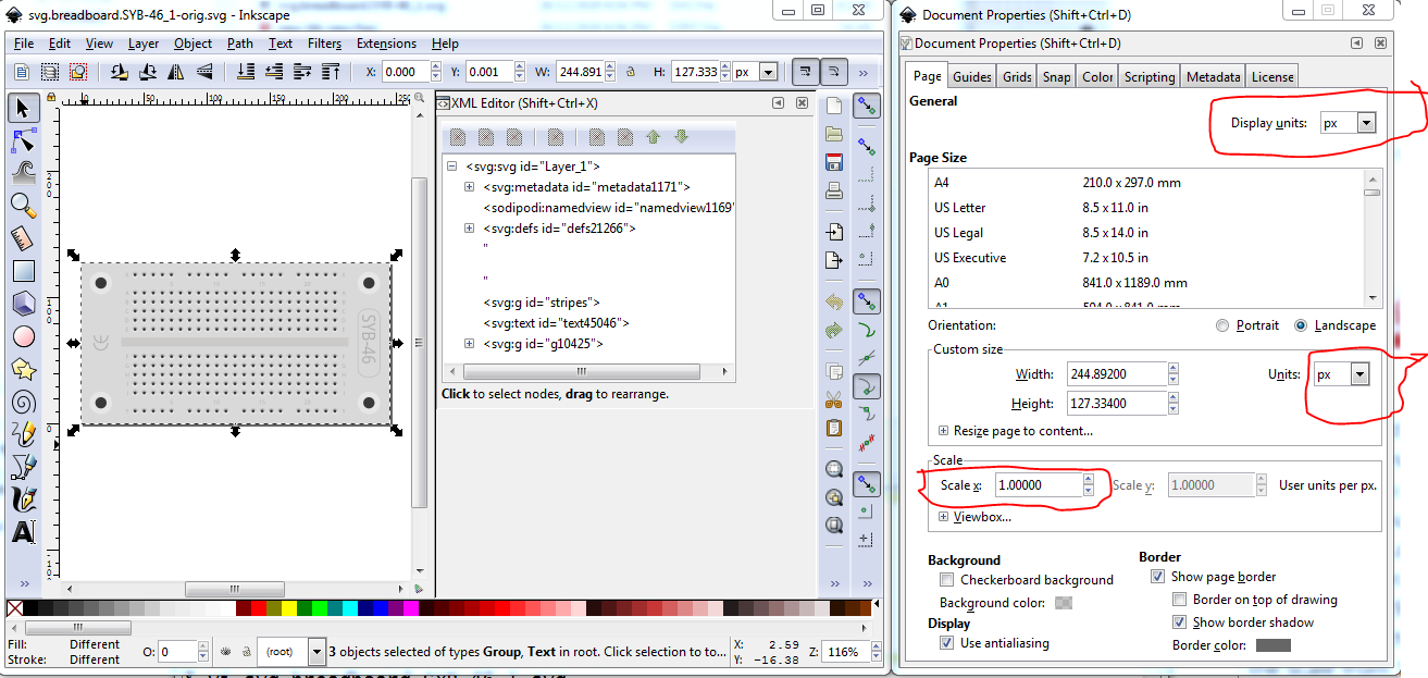
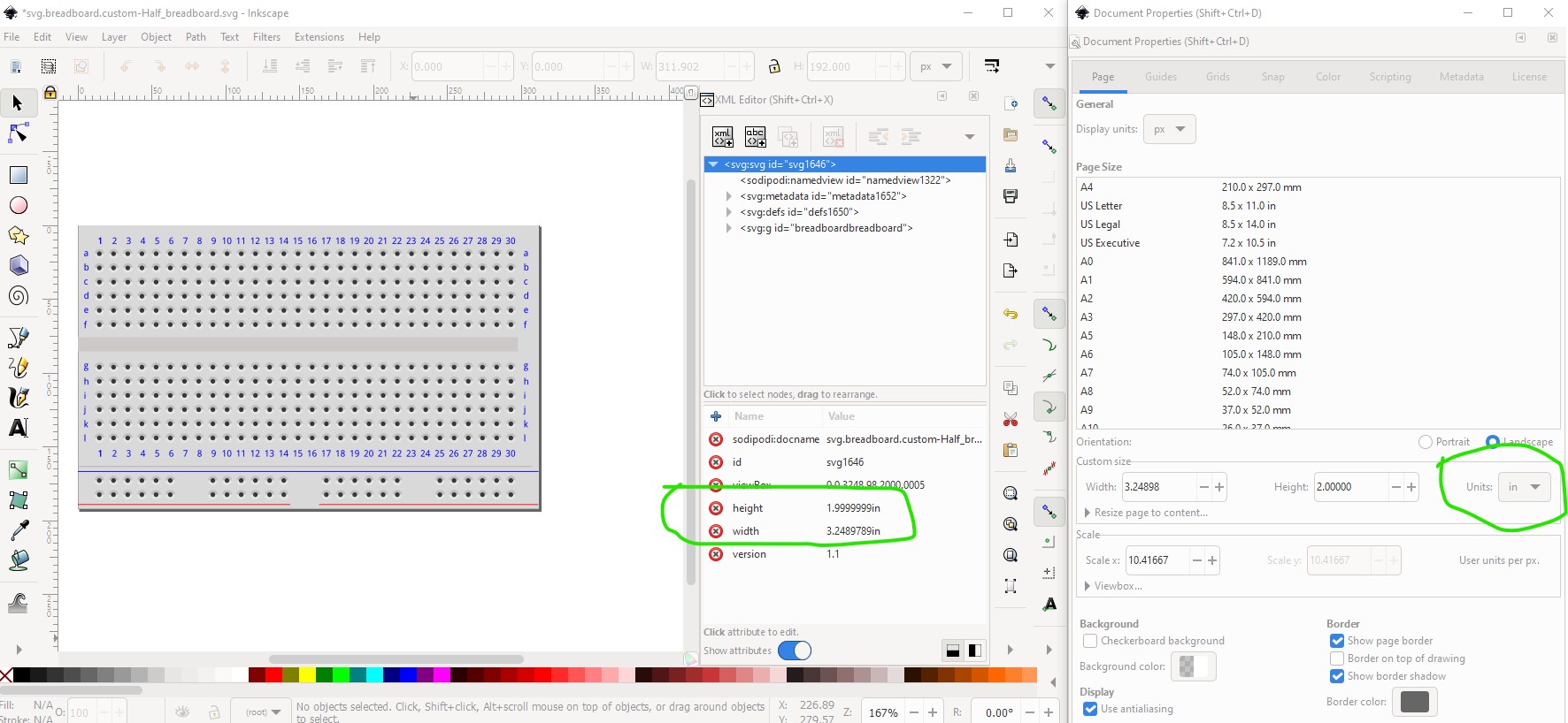
Your likely problem is that that the drawing is dimensioned in px (the original breadboard svgs are.) in 72dpi Illustrator. Current Inkscape is 96dpi thus the difference in size. The result is you need to rescale the svgs and set the dimension to in (or mm) not px. This tutorial may help:
Fritzing needs real world dimensions to reliably get the right size. “px” is a screen size, and the translation from that to really world units like inches or millimeters is not defined consistently. Different svg editors, and different versions of the same editor have defined that differently at different times. Fritzing tries to “guess” what the translation is supposed to be, based on other things in the svg file, but does not always get it right. This is one of the times it gets it wrong. So, to get this to work.
width="244.892px" height="127.334px"
needs to be changed to use units of “in” or “mm” instead of “px”, with the correct lengths in those units.
Also to note, the svg file does not contain the “breadboardbreadboard” layerId specified in the fzp file. The first group (g) element in the svg file has an id of “stripes”. That id needs to be “breadboardbreadboard”. Without that, the part will seem to work in Fritzing, but exporting the view to svg will not include the part.
That initial group element also includes a matrix transform. That has also been known to cause issues with Fritzing. To get rid of it, go back to Inkscape, select all, then ungroup several times. Group once, and set the id for the group to “breadboardbreadboard”.
This has the usual breadboard problems: the dimensions are in px (at 72 dpi from Illustrator as the breadboard was one of the first parts made.) Editing this in Inkscape (currently 96dpi) is what caused the size change. Unfortunately the pin IDs are groups, and ungrouping the svg (required to rescale it) will lose all the connector IDs. I’ll have a look, I think I corrected a half size breadboard (I know I did a full size one.) a while back. Your text problem is likely caused by not removing the px from the font-size statements in the svg. CSS demands the px on font size, Fritzing will set the font size to 0 if the px is present, so Inkscape output needs to be post processed before being fed to Fritzing. I use FritzingCheckPart.py (which also checks for other types of errors), but editing the svg and removing all instances of px works as well. As @microMerlin pointed out, you also need the breadboardbreadboard layerId to convince Fritzing this is a breadboard. As well all the elements need to be in a group with the breadboardbreadboard layerId.
Must have held my nose correctly, I managed to get Inkscape to rescale your svg without ungouping it when that usually screws up. Its possible there are not constructs the rescaling doesn’t like in a breadboard. This will make fixing the various breadboards in core much easier. Loaded the svg:
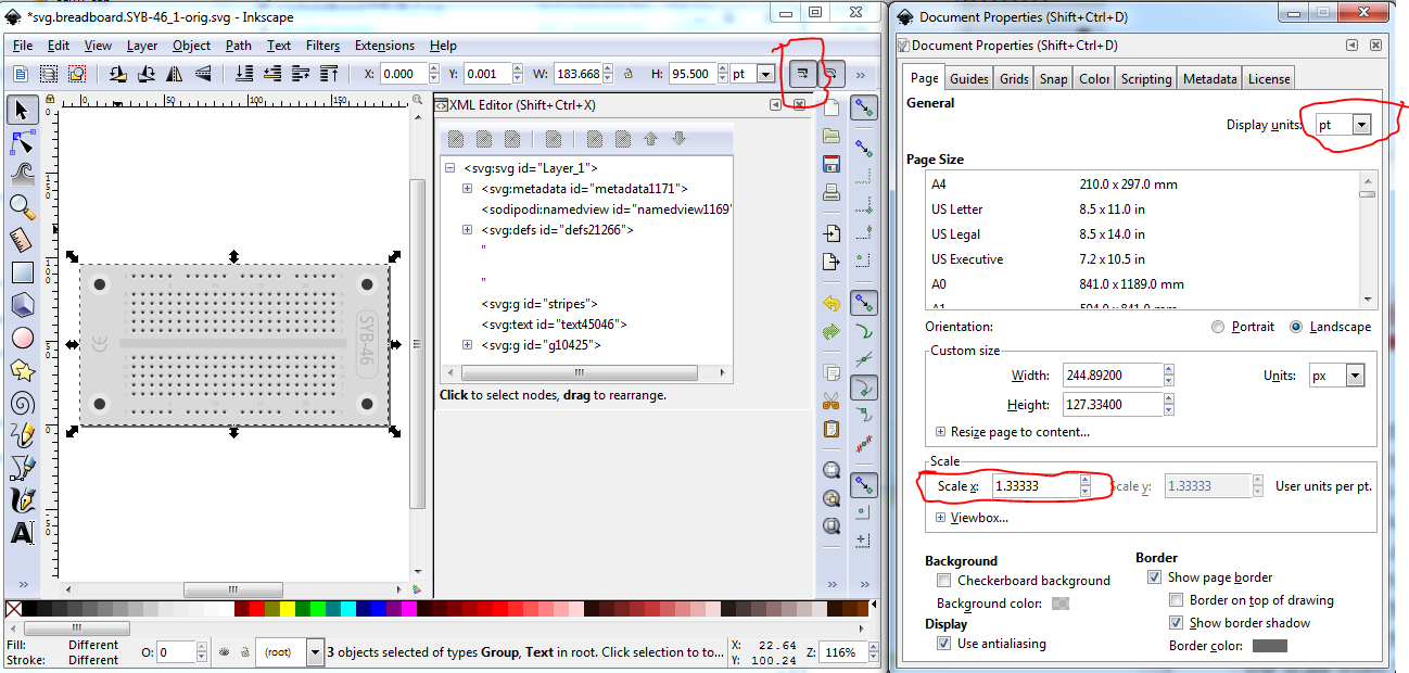
Check that scale stroke-width is enabled (red circled icon on the main tool bar), then set drawing units from px (96dpi) to pt (72dpi) which changes the scale from 1.0 to 1.333.
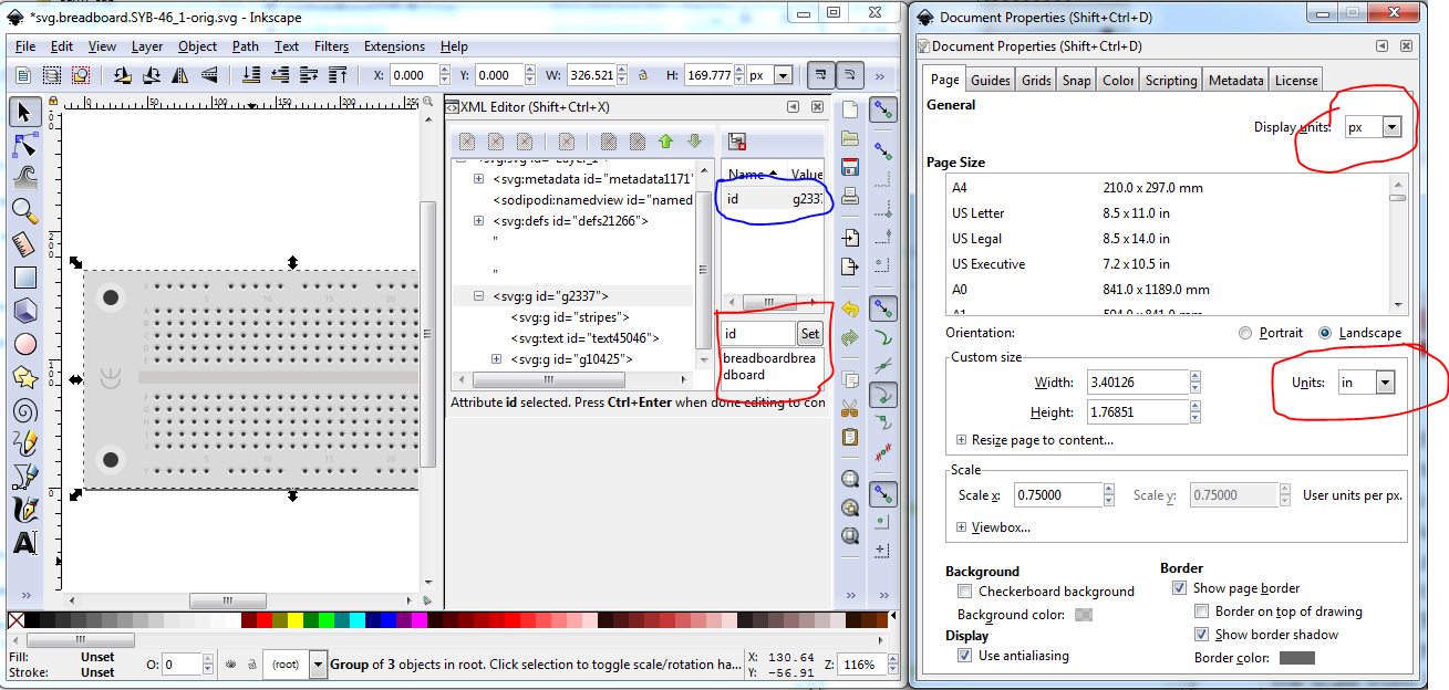
Edit->select all then set the scale back to 1.0, and then click on the canvass to make the scale take effect. The image gets larger, changes its origin, and size and deselects. Edit->select all Edit->Resize page to selection (to reset the view box to start at 0 0), change display units from pt back to px, change units from px to in (to avoid scaling problems in future). Object->group and set the group id to breadboardbreadboard. Save as plain svg.
run the resulting svg through FritzingCheckPart.py (which complains a lot because this is a breadboard!) to remove the px from the font size in the svg, recreate the fzpz file and all is well.
Hi, I’m new to fritzing but have a similar problem and have to use a specific breadboard which is not included. I’ve re-created it in illustrator and exported as SVG but I don’t know where to start with importing it into fritzing. I’ve tried following tutorials online and reading this but i still can’t create the part. Any help would be much appreciated.
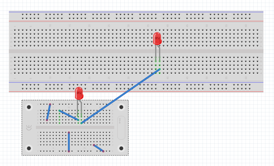
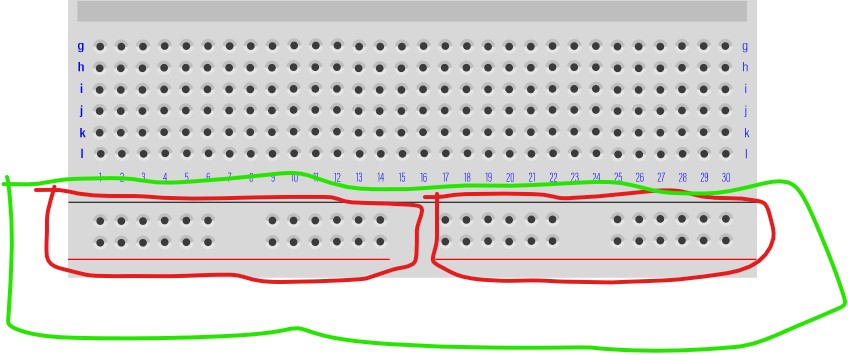
We need to know if the two power strips are separate (the red circles which seems likely) or tied together (the green circle.) as it affects the buses.
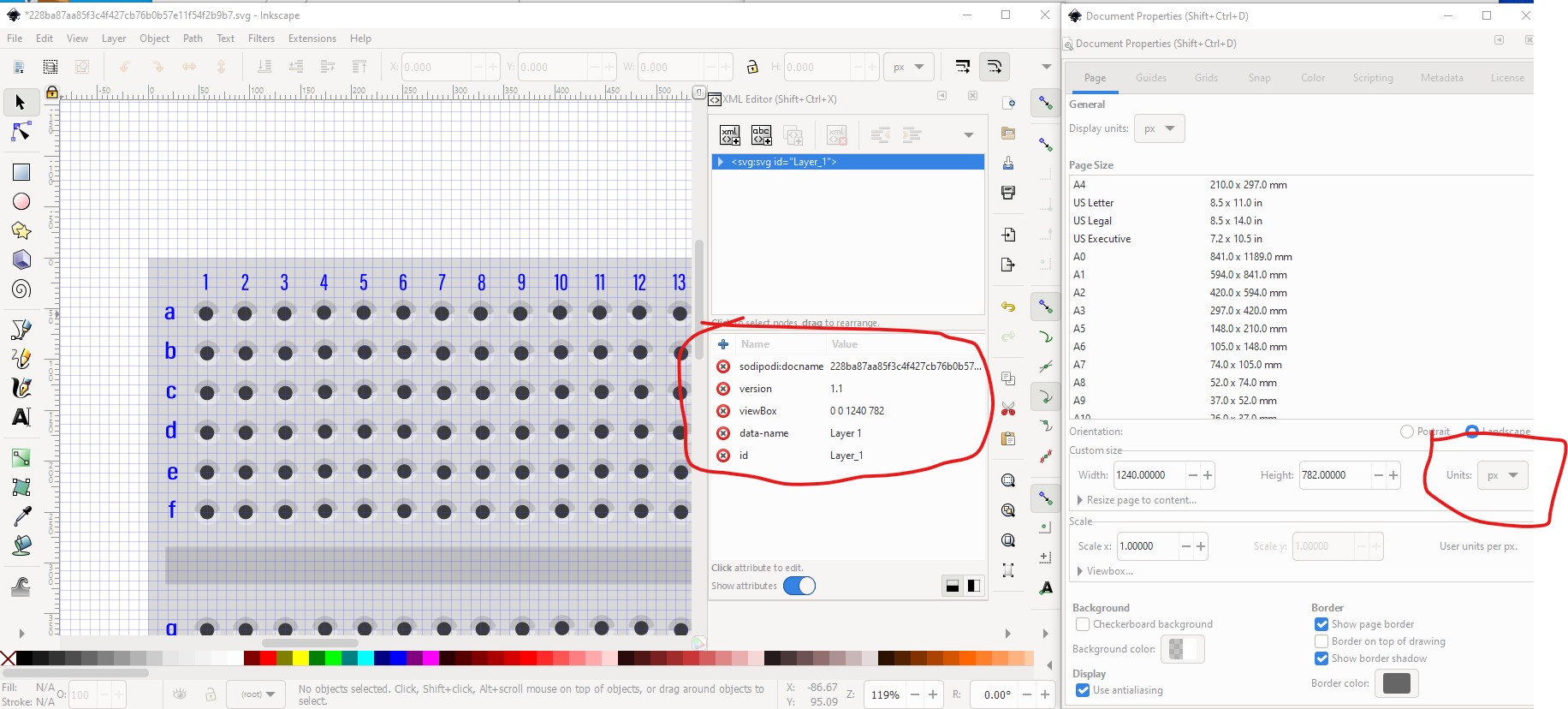
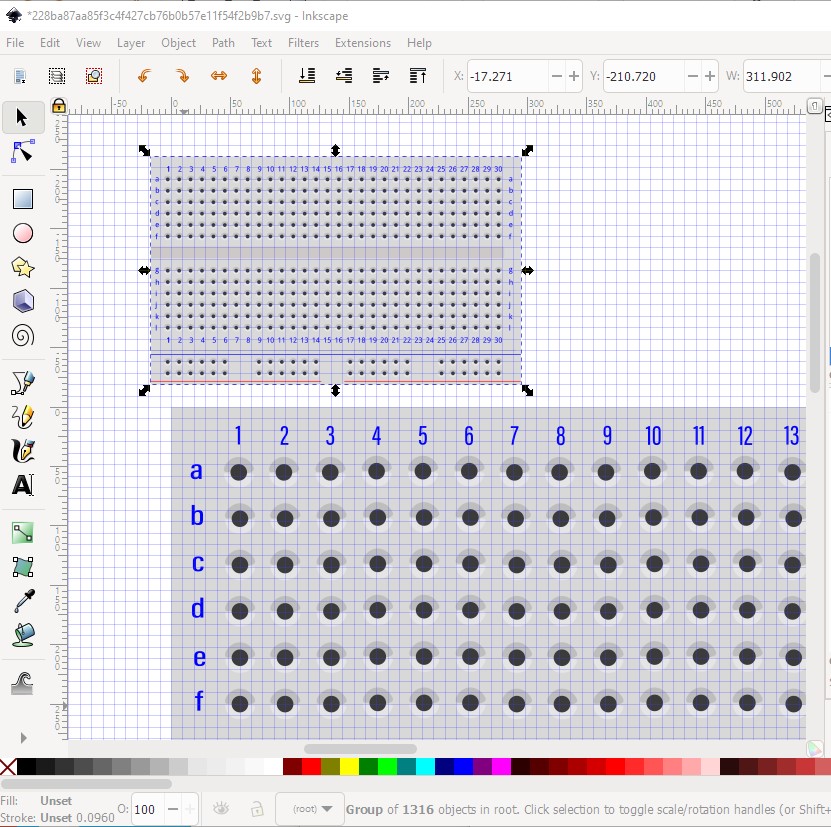
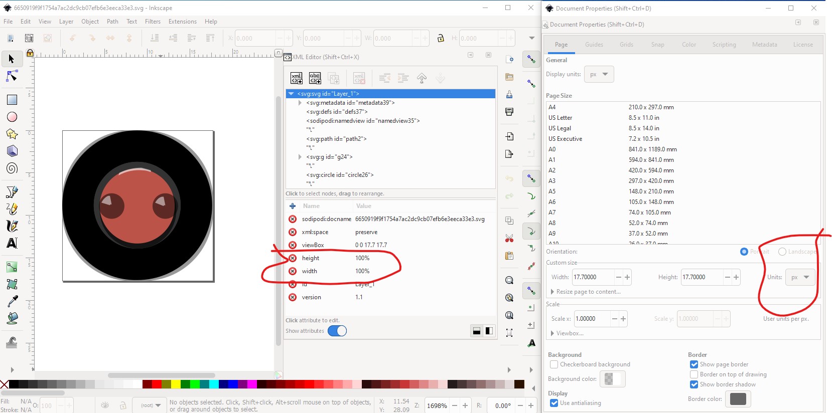
Your svg has a scaling problem (and I don’t know how to fix it in Illustrator as far as I can see from the documentation, there isn’t a way to set the dimensions to inches it always uses px!)
In Inkscape here the grid is set to .1 in and as you see your svg is much too large (the pins should be 0.1in apart.) There is a viewbox but no real world height or width specified and the dimensions are in px (as they have no units) which is a problem in Fritzing because it depends on the DPI setting of the editor and Fritzing will guess between 72DPI for original Illustrator and 90DPI (the old svg standard which is now 96DPI which Fritzing doesn’t recognize at all!) For comparison here is my final svg copied in to yours:
as you see the document dimensions are in inches and the height and width of the drawing are specified in inches (rather than px which is what is assumed if there are no dimensions or px specified for height and width. Since an inch is always an inch Fritzing doesn’t need to guess and will set the scale correctly.
This works perfectly thankyou! I’ll make sure I check the size next time as well and put it into inches.
I’ve just attempted to create a smaller button which goes over 2 pins but I can’t get the sizing right when I put it into fritzing as it’s still way too big.
Same issue, there are no real world sizes in the svg so Fritzing is making a guess at the size and getting it wrong (probably using 72DPI as the units making the image too large.) You need to get the first line to have dimensions in either inches or mm for the height and width but I don’t see a way to do that in the Illustrator documents.
Depending where you need that 4 versus 5 pins, Fritzing already does it.
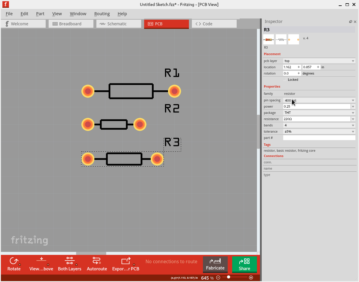
If you want to change the lead spacing on PCB view, select a resistor (any view, after it has been placed), then in the Inspector window, change the “pin spacing” value. That can be changed from 100 mil (.1 in) up to 800 mil. However that only affects the footprint used for PCB view.
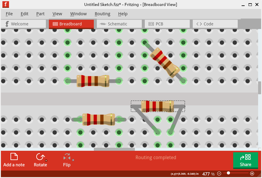
If you want to change the number of breadboard columns the resistor spans, there are different options. Rotating a resistor 45° lines up nicely for 4 rows instead of 5. To keep horizontal, resistors have bendable legs. Dragging the yellow connection point inward toward the resistor body works, to reduce the distance from .5 to .4 inches. More extreme changes are also possible.