Hi,
i am new to PCB layout and fritzing and i could not figure out how to create a layout for this component. Where can i find solid information on how to create custom components.
Thanks a lot.
Hi,
i am new to PCB layout and fritzing and i could not figure out how to create a layout for this component. Where can i find solid information on how to create custom components.
Thanks a lot.
That’s a hard one.
I know its not very helpful, but I think the holes are a hard one to do. I have been trying to do some SMD layouts all day in Firtzing and the best source I have found is here.
But it may help you do everything you need, but its a place to start.
A.
Thank you for your answer. Good to know that i am not the only one having a hard time to understand frizzing and custom parts.
I was able to make some parts last night that are close to yours.
I may try to make a video on how I did it, but here is the basic outline.
find a part that is close to the one you need. If you need mounting holes and contact points than I suggest you search for the PCB layout of the BNC connector in your parts>svg>core>pcb folder.
open the svg in Inkscape and look at the XML editor. find the lines that control the holes, and the contacts.
Open the part again notepad++ and copy and paste the components that you need more of. (change some ID’s and some X and Y coordinates.)
Back in inkscape open the XML editor and click on a line to edit it.
I was able to make the PCB outline for this SMA connector,
http://www.digikey.com/scripts/DkSearch/dksus.dll?Detail&itemSeq=186248246&uq=635864768755049218
I also this this Inkscape and notepad++ to make some SMD layouts. (VSSOP-10 and TSSOP - 16).
I know this is vague, but maybe it helps.
2 more things.
Save your SVG’s in Inkscape as plain SVG’s. (wasted a day on that)
You can edit the Schematics in Inkscape using the XML editor. This helps to keep everything clean.
Thank you very much. The BNC connector hint did really help a lot.
Were you able to get your part working?
If needed I could make a short video on how I did mine. I was going to anyways but I am waiting to see what the parts editor looks like in Feb (if its on the re release).
Hey. Thanks a lot for asking. I finally got my custom parts together. Took me almost 2 days. My next problem now is that i can’t get the routing to work. The schematic and the PCB views don’t match. But thats another story. 
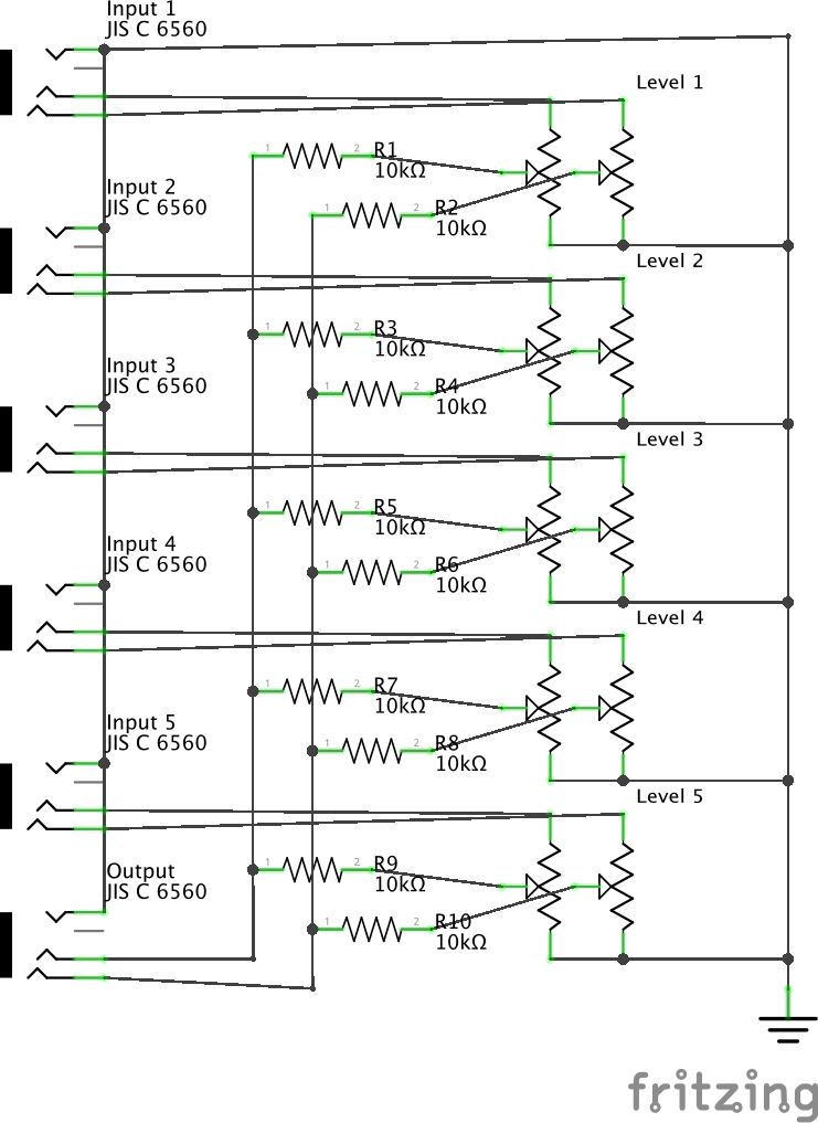
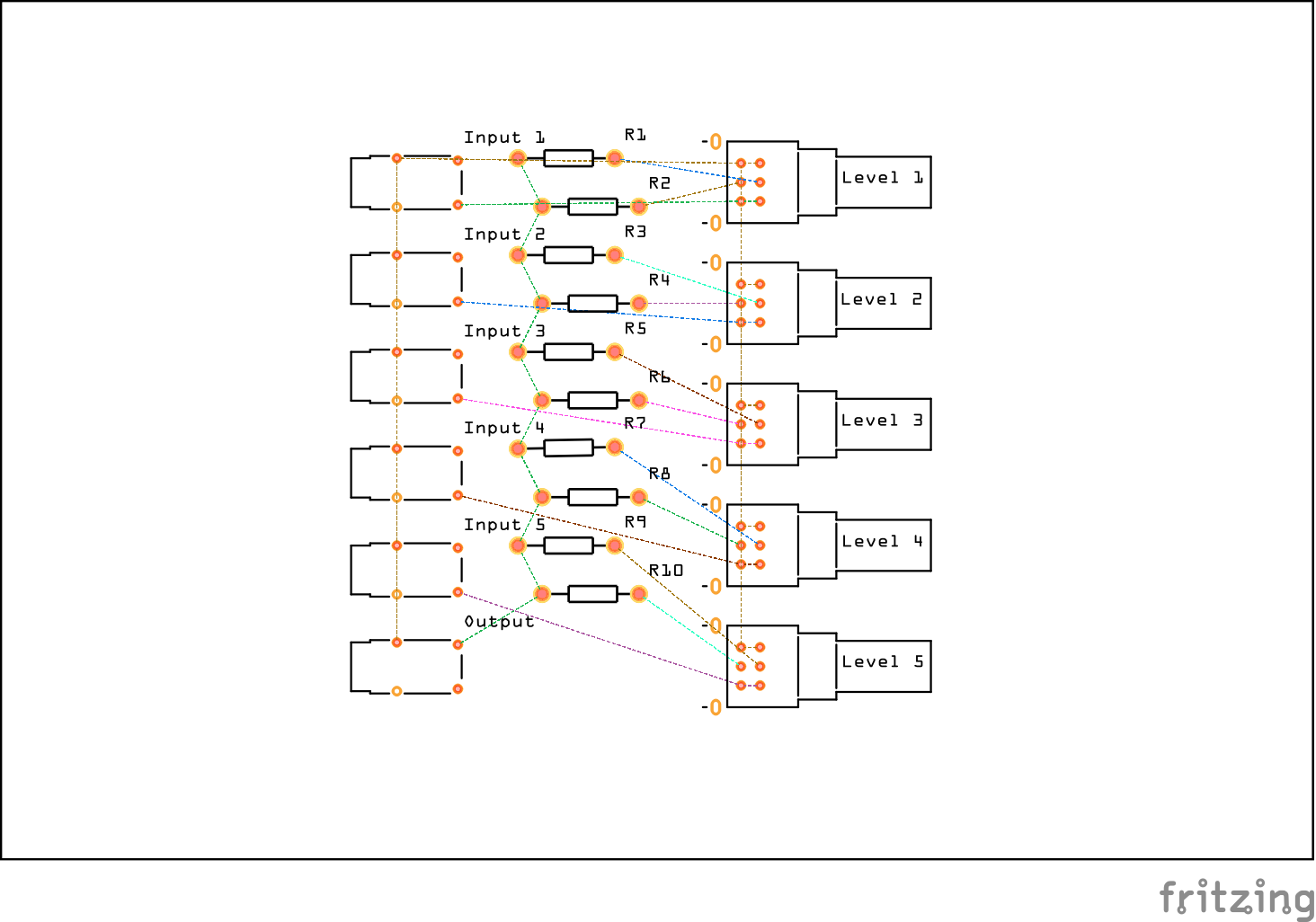
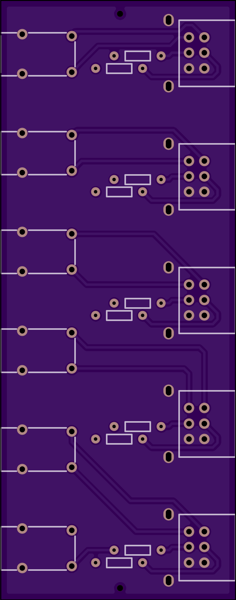
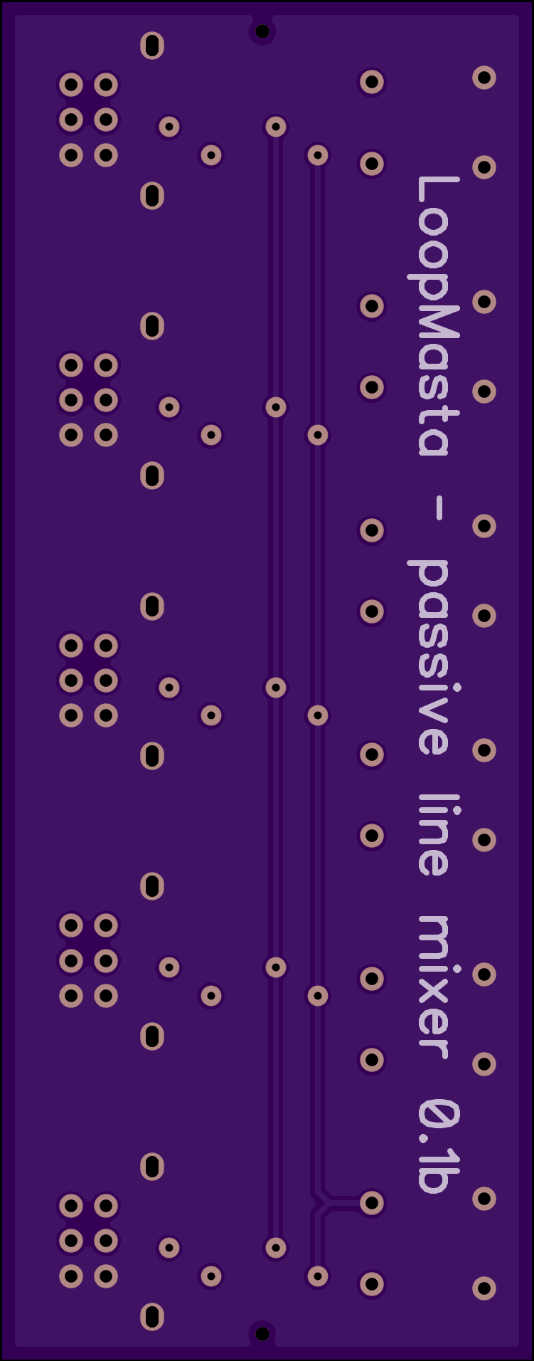
This is ok.
This is wrong. See the left hand side connections of the resistors!
I have been thinking abut this for a few days.
Are the pins on your jacks connected in the part as “internal connectors”? The auto route would interpret this as as the two resistors need to be connected on the left side, resulting in the PCB view you have.
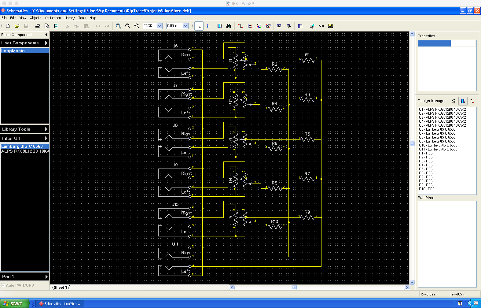
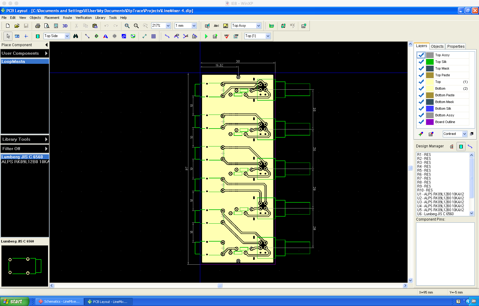
@tex_downey After a week of struggling with Fritzing i decided to take a look at some other layout tools. I found diptrace a windows application but because i am working on a macbook i installed a free version of diptrace on a VMWare virtual PC and started from scratch. I learned how to use diptrace, created my two custom parts, the schematics, the layout and after only a day my board was done.
I exported the project as gerber files and uploaded it to OSHpark to do the actual PCB printing.
The uploaded files passed the OSHpark test procedure and while i am writing this my board gets printed and shipped in 5 business days.
Too sum up my experience. I love Fritzing, the fact that it’s open-source and its community and i really tried hard to make it work but in the end it was easier and faster for me to install a limited free version of a commercial pc app to a virtual machine to get my board done. I think in my case the main show-stopper was the parts-editor with its SVG input.
I understand completely. Fritzing is easy to learn and great for simple projects but the parts editor function is still a work in progress. That is why I am trying to spend some time on the forums to help others out and build a documentation base for anyone who has a problems.
might be worth making a note of some useful youtube videos I found for part making in fritzing they are in english
Making Parts in Fritzing 2014
Making Custom Pars in Fritzing
not sure if this would help others but I was going to post about wanting help making some new parts for fritzing but saw this and then thought it would be worth posting here instead
another link I found is this one
Thanks for sharing my video. I to find the fritzings parts editor to be the worst part of fritzing and I hope the video will help others. I was able to make some custom pads for a no-lead QFN so I could hand solder it.