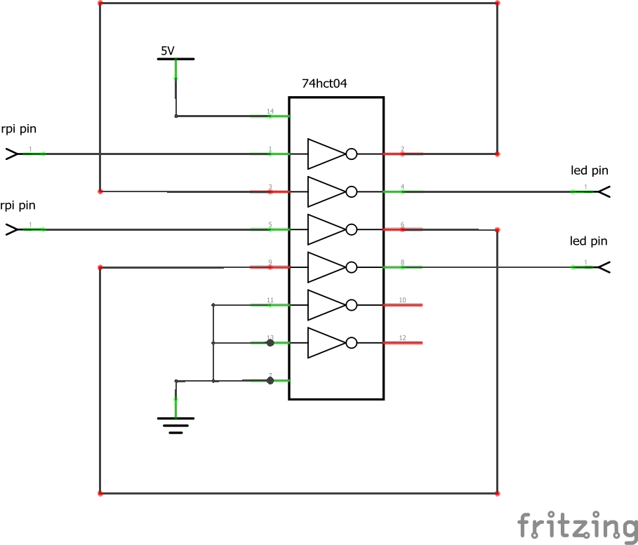
The first thing that I would advise is don’t use any of the TXBs (or any of the other) “automatic direction sensing” translators. They tend to not work when the load gets toolarge causing very hard to find problems. That is especially true of these LED devices as the clock timing is very tight. Since this looks to be output only (not bidirectional) your best bet would be something like a 74hct04 hex inverter chip in place of the TXB0108, actually what you want is a 74hct126 quad tristate buffer, but I don’t see a Fritzing part for that. This schematic will do what you want. Two inverters are used to make the output signal non inverted. The hct input high voltage is 2.4 volts so the 3.3V output from the pi is high enough to drive it. and it in turn will drive the LED at 5V.
I like this hack https://hackaday.com/2017/01/20/cheating-at-5v-ws2812-control-to-use-a-3-3v-data-line/ where you run the first LED off of a 4.3v Zener diode and since these are triggered at 0.7 * input votage and the output is input voltage you get a step up from the 3.3v to 4.3v to 5v and the extra LED is a faster level shifter than most dedicated level shifters.
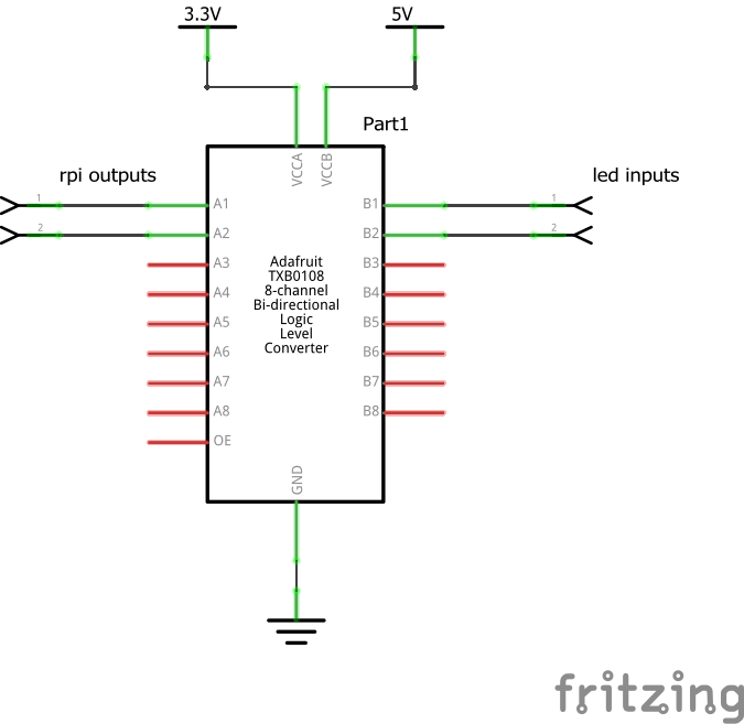
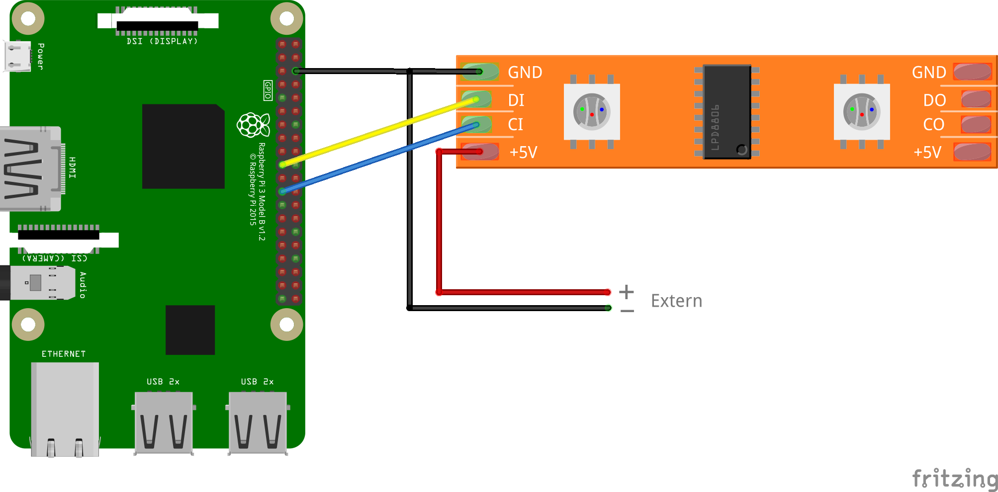
Assuming the device on the right is the leds, there currently doesn’t appear to be a level shifter in the circuit. If you have to use the txb then this circuit should do what you want (you may need to ground the unused terminals on the txb). VCCa gets 3.3V from the PI, VCCb gets 5V from the led string. If the load is low enough this may work successfully. You probably want to only drive 1 led input with the txb output as load is what breaks them.
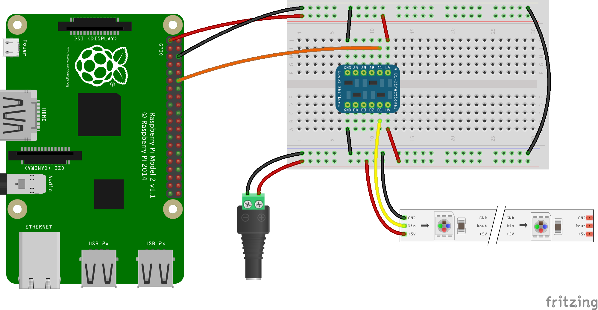
I grabbed the Fritzing part for the txb0108 from the adafruit frtizing library (google will find it) as it isn’t in core parts. Basically the yellow and blue wires from the PI go to the A side of the level translator and the same output pin on the level shifter on the B side goes to DI and CI on the LED device.
