Hi everyone!
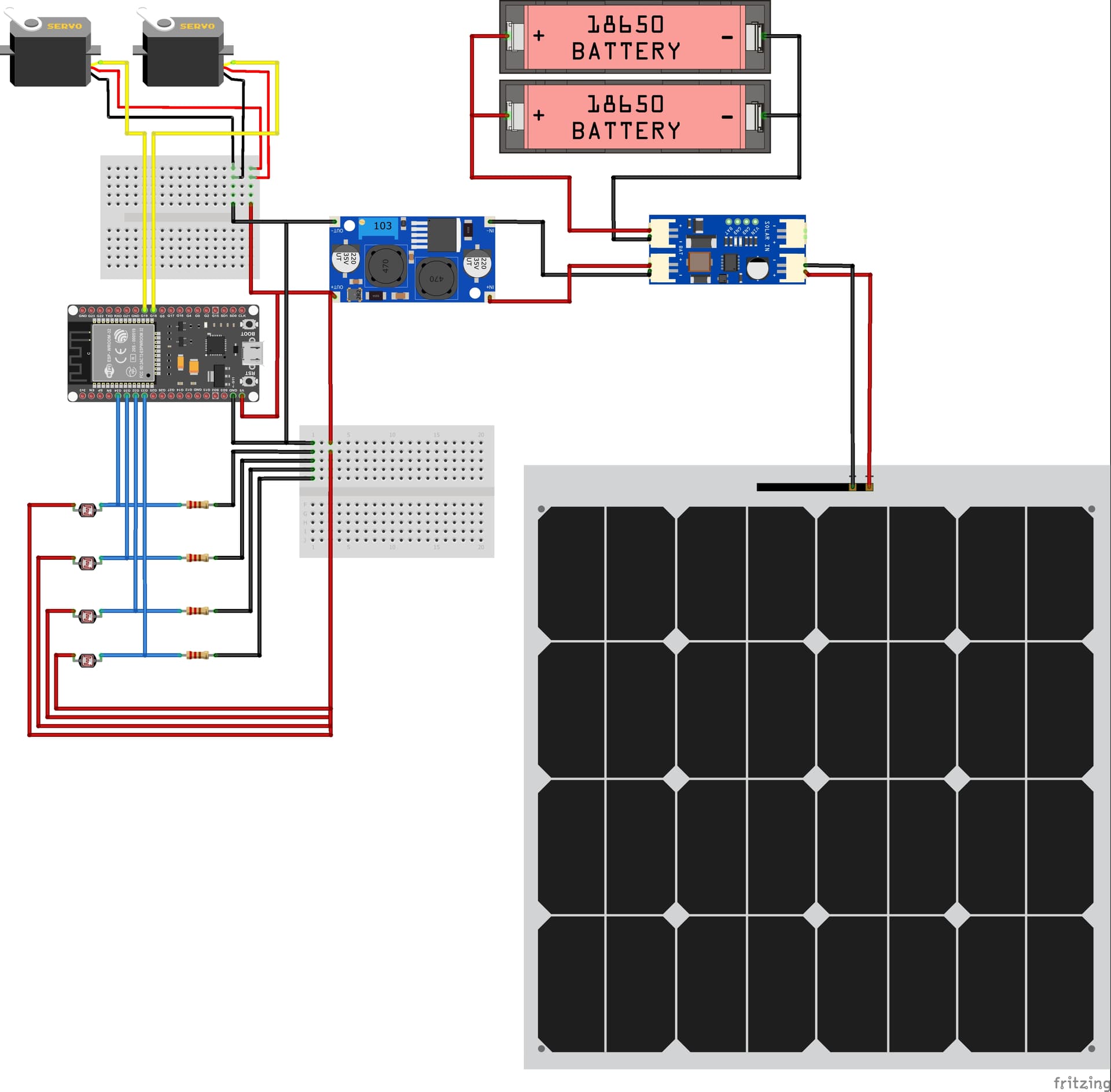
I’m currently working on a prototype for a dual-axis solar tracker using ESP32 and 4 LDR sensors, powered by two 18650 batteries and a solar panel.
I want to use an INA219 module to measure the current and voltage from the solar panel (or battery output), but I’m not sure how to properly connect it to the rest of my circuit in Fritzing. I’ve attached my current schematic (see image).
Could someone help me:
- Figure out how to place and wire the INA219 correctly in this setup?
- Check if my current wiring is correct or if there’s anything wrong or risky?
- Give suggestions on how I can improve or optimize the circuit overall?
Any feedback or example would be much appreciated. Thank you!
@putrapasha It will be good if you can attach the .fzz sketch file (not .fz) There is an upload button in the forum that allows you to add files
I’ve attached the .fzz file of my circuit as well.
Feel free to check it and let me know if there are any mistakes in the wiring or suggestions for improvement.
I’m open to any advice to make the circuit more efficient and stable. Thank you!
ASTRA.fzz (84.8 KB)
1 Like
What INA board are you going to use? Adafruit?
No, seems find. Just check the part(s)’ datasheet to double-check’
I’ve added a breadboard for neatness.
ASTRA-improved.fzz (79.9 KB)
Thank you for the response!
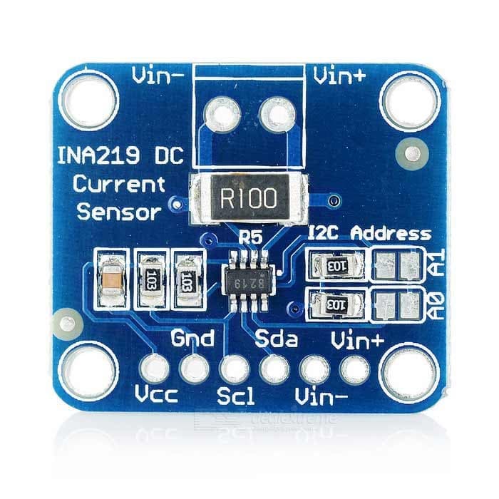
I’m using the generic INA219 module something like in the image, so I’ll double-check the pin layout just to be sure.
Appreciate you reviewing the wiring also thanks for the tip on adding the breadboard
1 Like