So I’ve been trying to do this for an embarrassingly long period of time before asking for help.
I have one wire from my power supply that I would like to run to two stepper motor drivers. In other words I would like to split the wire or create a junction" in the middle that can go to another pad. But I can’t get it to work. It must be possible - what’s the secret??
Can this be done in breadboard or only in schematic?
Start from the unconnected terminal and drag a wire to the shared terminal (trying to start at the connected terminal will usually move the wire instead of creating a new one.)
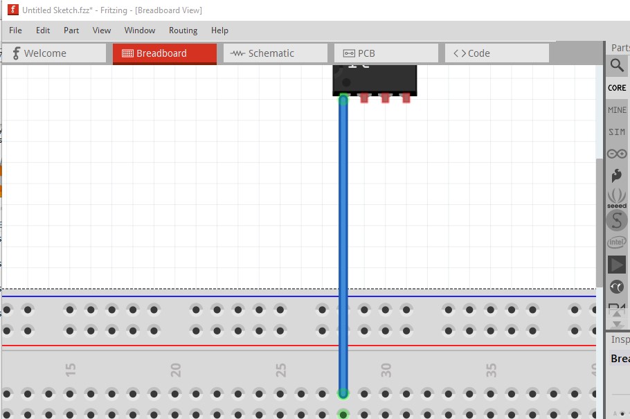
Assuming that you mean you want to connect to the middle of a wire in breadboard view.
Extending on Peter’s solution, as long as you have align to grid enabled, it is easy position one wire directly on top of another for part of the path. That makes the overlaid section look like a single wire.
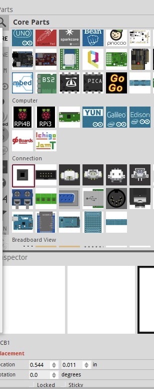
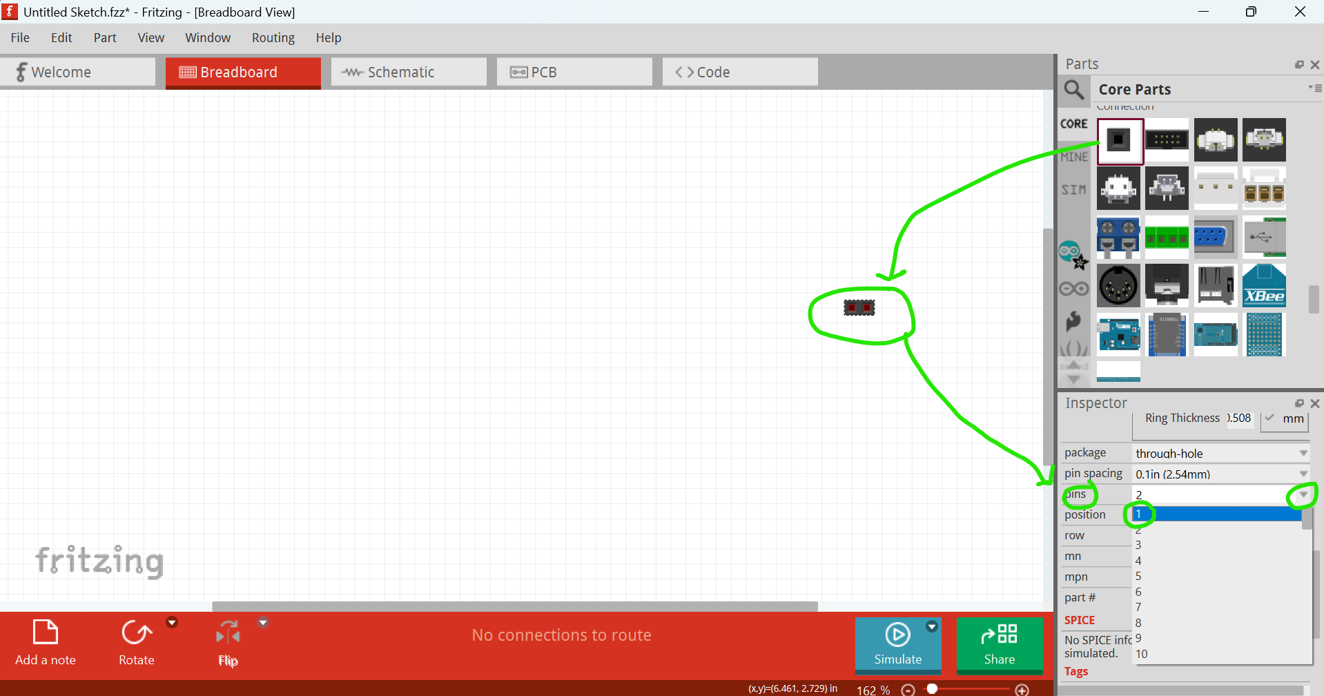
Another alternative is to use a ‘dummy’ connector. Place a pin header (first entry in the ‘connection’ block for core parts). Use inspector to change that to a single pin. Now connect as many wires as you want to the connector where the wire split is supposed to occur. It can be a bit tricky to select the connection, to be able to move it. To make that easier, temporarily turn off the (view for) the wires layer. Move the connector, then turn the wire layer back on.
On other views, you can end a wire at a bend point in an existing wire. That ‘merges’ cleanly, and can be moved afterwards. At last for just a 3 way join. I have had glitches when more than 3 wires are joined at a single intersection.
I can’t find the dummy connector. The first entry in the connection block for me is “Generic Female Header - 2 Pins”. I tried to use it but I can’t change its properties (not editable).
I also tried ending a wire at a bend point in an existing wire. That also doesn’t work. What am I missing?
How does the generic header look like? I searched for header but I got too many results.
As I mentioned, I found the “Generic Female Header - 2 pins” but it doesn’t work. I can’t change it to have only one pin. It’s properties are not editable.
BTW, I tried inserting an LED. It was labelled as Red 663 nm LED. It turns out that I can’t edit the property of this LED to change its colour. Does it mean that there’s something wrong with the parts database inside my installation of Fritzing?
Is that why I can’t find the generic connector you mentioned?
Parts need to be placed in (dragged to) a sketch view before their properties can be edited with inspector. Before they are in a sketch, the parts are part of the library, and are read only. Don’t want to modify a part when it is still in the library.