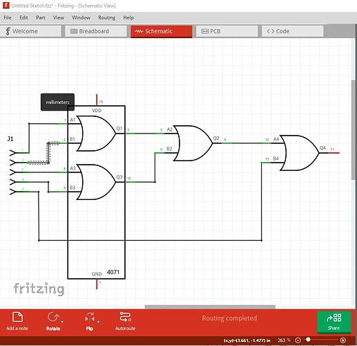
There was a post from 2021 about drawing a logic circuit in Fritzing, and the image below shows such a diagram. I just don’t know where to find the logic circuit symbols (AND, OR, NOT, etc.). They don’t appear to be in the parts bin. Thank you for your help.
They aren’t in the parts bin, they are in the specific part (the 4071 cmos or gate in this case.) There are some but not all chips around some in core parts more available via a google search for “fritzing part 4071” (where 4071 is the name of the part you want such as 74x125.) If the search doesn’t find anything then someone would need to make a custom part which may happen if you ask (making parts is fairly complex, although you are welcome to try and we will assist!)
There are some in core parts (mostly the 4000 series) but more are available on the net. Some parts don’t have the internal logic drawings, so you need to look at schematic of the part you choose to see if it is suitable.
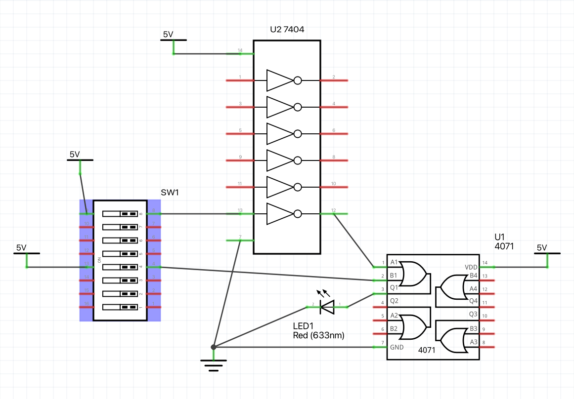
You can make a neater schematic with different parts. Here I used the 4071 multi version and the 7404 from this post (which both have schematic subparts)
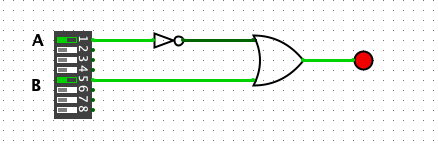
The subpart type parts allow you to move a single element of the gate around like this:
the wires don’t end in the center of the pin because both these parts are properly configured with a schematic terminalId so the wire ends at the end of the pin not the middle. Here is the sketch that produced the above image.