Hello,
Sorry if my question feels dump 
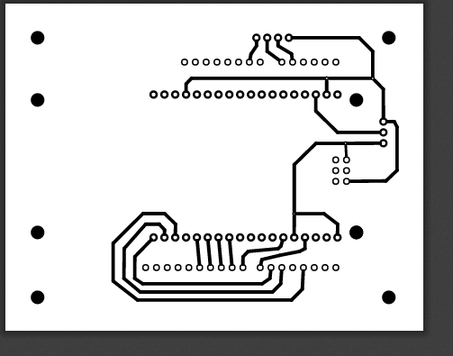
I am using pdf export for later one side etching (the chemical process). typically i would use the following file printed in a transparent sheet
myproject_etch_copper_bottom_mirror.pdf
Once the board is etched, we use a manual milling machine to make hole and a circular saw to cut the sides.
My problem is that i would like the outside boundary of the PCB board to be etched too so that i known exactly where to cut. Right now we try to measure with a ruler draw the sides with permanent ink pen. So each board as sligthly different sizes 
For the record, the file myproject_etch_silk_bottom_mirror.pdf does show the outside boundaries ot the PCB board but without the mounting holes so it’s hard to align
Is there some sort of option to make the outside dimension of the board to appear in the etch copper pdf file ? or should i just try to manually create 4 “fake wires” drawing the outside boundaries manually ? (not tried yet)
any idea ?
thanks
fourchette
I don’t think it can do it, at least I’m not aware how to do it.
What you can do is put a via in each corner and join with tracks to make a rectangle, and then cut to the inside of the rectangle.
If it was me doing it at home, and I was doing a lot of these, I would change the outer 4 mounting holes for 0.5mm vias. The small centre vias will centre the drill and accurately drill them in the centre. I would then mark one and stack a bunch, using drills as dowels, and cut them in a stack.
I actually put a 0.5mm via on all my contacts so they get drilled accurately in the centre, and even silkscreen/toner transfer the other side.
https://www.mediafire.com/convkey/25c3/5frw7k227ry18a86g.jpg
There is more than one way to skin a cat…  well… not that kind of cat…
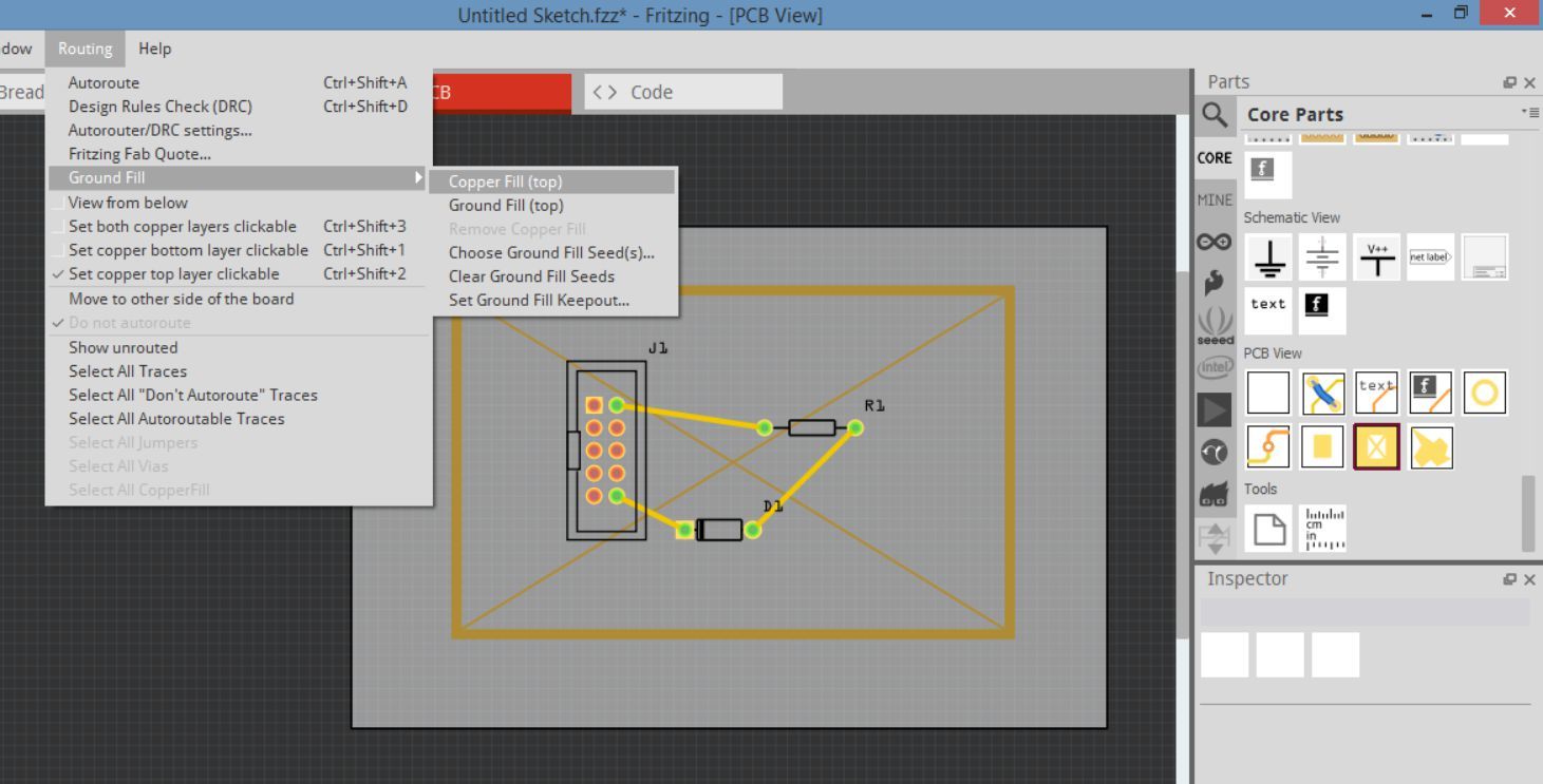
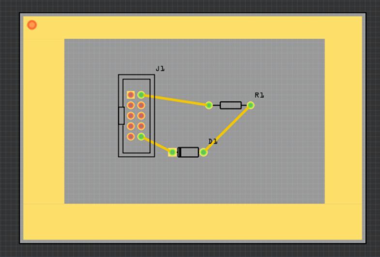
Place the Copper Fill Blocker on the board, framing the saw line border… then click Routing, Copper Fill, then Copper Fill().
You can remove the Copper Fill Blocker. If you are not using Copper Fill then just cut around the copper edge.
If you are using copper/ground fill, then right click on the copper fill border, then click Lock Part. Once again, click Routing, Copper Fill, then Copper Fill() or Ground Fill(). Then just cut around the the Copper Fill Keepout… 
After I posted I was thinking that maybe copper blocker and copper pad might be able to do it, seams like it copper blocker and ground fill. Cool.
Also thought about ‘for production’ svg, and just add it in Inkscape. The only problem is you can’t scale a print in Inkscape to get contact position perfect.
