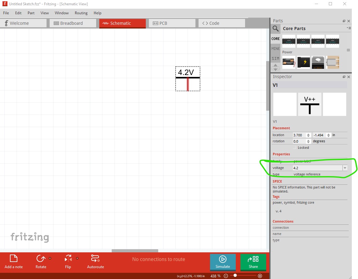
Why is Fritzing limited to just offering 1.2V, 2.4V, 3.0V, 3.7V, 4.8V, 9V power voltages? Also, is there no adjustable power supply where I can input whatever voltage I would like? I’d like to use Fritzing to design circuits that are powered by fully charged lipo battery cells (4.2V) so that I can see how the circuit will behave at 4.2V and not at the lipo’s depleted state of 3.7V.
Why do you think the voltage is limited to those in the pull down menu? You can type any voltage you like in the text field in Inspector like this:
Peter
1 Like
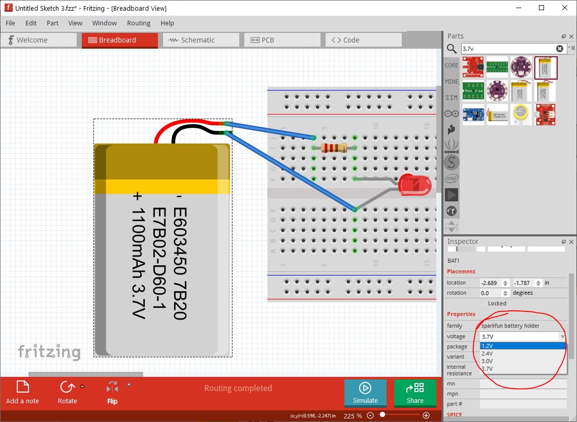
Vanepp, thank you for your response. My issue is related to the breadboard tab (see screenshot) where the dropdown menu only offers 1.2V, 2.4V, 3.0V & 3.7V. It doesn’t allow any other values to be entered. Note that I did follow what you suggested and it did allow me to enter any voltage I wanted under Schematic tab but when I switch back to Breadboard tab that voltage supply doesn’t transfer over.
Doesn’t look like the code will let you do that in breadboard so it appears you are restricted to setting a voltage source in schematic.
Peter
1 Like
probably because in breadboard the voltage is tied to which graphic image is used. You might be able to use a more generic ‘power supply’ part, and change the voltage on that.
1 Like
In addition, the voltage symbols in the sch view do not power the circuit in the simulator. You still need to add a power source.
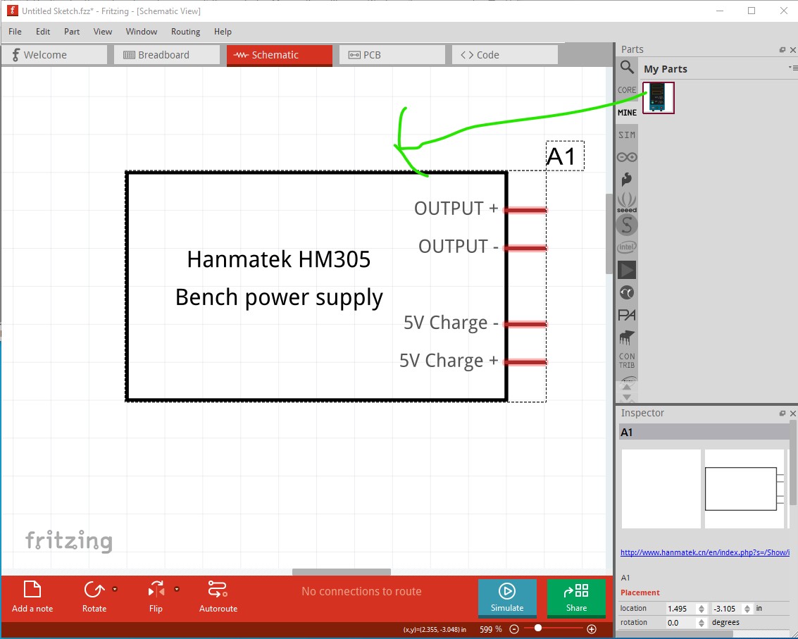
@vanepp made a lab power supply, maybe you can use it.
1 Like
Fai, I imported @vanepp lab power supply which is exactly what I was looking for, however, it appears that is just a graphic without the capability to simulate an actual power supply.
@vanepp, do you plan to develop your lab power supply further where it will actually function as a power source in the breadboard simulator?
Nope, because I don’t know how to do that. I believe @fai is going to need to (or perhaps already has?) change the code in the simulator to read the voltage and current settings from the part (they are currently blank but you can add text to them to set values, those values then need to get in to the simulator somehow.)
Peter
1 Like
@vanepp , you can do it. It should not be difficult. The simulator reads the properties of the parts. So, you need to add a voltage property in the part. I think you also an internal resistance property (set it to 0.1ohms or lower).Then, you need to add the spice model, which is the same as the in a battery.
<properties
<property name=“voltage” showInLabel=“yes” 9V</property
<property name="internal resistance"0.1Ω</property
</properties
<spice>
    <line>V{instanceTitle} {net connector1}_{instanceTitle}_aux {net connector0} DC {voltage}</line>
    <line>R{instanceTitle} {net connector1}_{instanceTitle}_aux {net connector1} {internal resistance}</line>
</spice>
Edit: the forum cannot display the XML code of properties. I remove the > symbols so the forum shows the code, but of course, you need to add then in the fpz.
That should be enough for the simulator, but the user would need to change the voltage property in the fpz file, which is not practical. So, you need to change the module id of the part so ends in “DC2PowerModuleID”. That will activate the properties mechanism of Fritzing and the value of the voltage can be set in the inspector page.
Let me know if you have problems!
1 Like
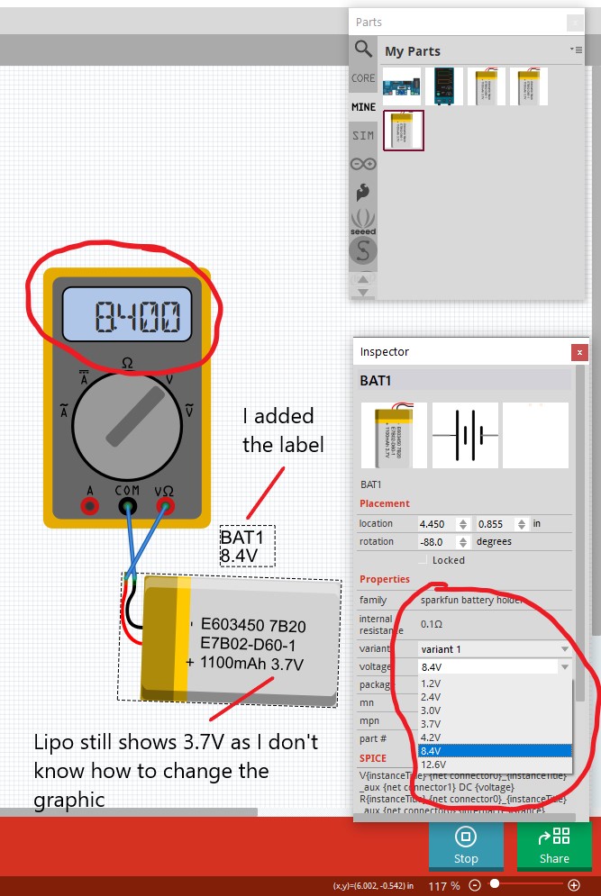
Success at last!! I can now add a lipo battery which will allow me to select any voltage that I want.
In my case, I set it up for 4.2V, 8.4V or 12.6V from the dropdown menu!! It works in both the Breadboard View as well as in Schematic View. It was actually quite simple BUT quite quirky to get it setup. If anyone is interested, I can provide details on how. In short, I simply created a new part based on the already existing 3.7V lipo battery that I found in the parts bin. Thanks for everyone’s help!
I did it.
To change the battery graphic you need to edit the breadboard svg with a svg edit such as Inkscape, change the voltage text and then reload the svg in parts editor. You would need different parts for each voltage as AFAIK you can’t modify and svg value from the parts properties (the chip label field however may allow this if you replace the 3.7V label with the id label and set the value in the chip label property.)
Peter
1 Like
Well done!
3.7 is the nominal voltage. I would not worry in changing it. When you use a battery you know that it will be above the nominal voltage when fully charged and below it when it’s empty. This happens too with a physical battery.
1 Like
Not for a 2 cell 8.2V battery which is what he is trying to make.
Peter
1 Like
fai & vanepp…thanks for your support! I’m not even gonna worry about changing the 3.7V label at this point. Just figured I would point it out to anyone who may see me posting a 2 cell lipo which is labeled incorrectly as 3.7V
It looks like there is something wrong with the moduleId postfix. This moduleId
module moduleId=“hanmatek-HM305_2-DC2PowerModuleID”
causes this:
breadboard doesn’t render (but does if the normal moduleId is used) schematic is fine so the part is loading
looks like only dcpower2.fzp uses that moduleId (and it isn’t a pre or post fix just a straight moduleId
moduleId=“DC2PowerModuleID”
so I expect I need a different postfix but don’t know what.
Peter
Of course! I thought he just wanted the 4.2V battery
I just tried this and I can reproduce the issue. I checked and there is code in Fritzing that disables the BB view if the moduleID ends in DC2PowerModuleID. A trick could be to use the “CapacitorModuleID” at the end of the moduleID. That will enable that users can change the property in the inspector, but the voltage will not be able to be less than 5V (as defined in properties.xml). A nicer fix would be to create a new moduleID, but needs a change in the code.
@pcgraphix , how did you manage to change the voltage and still have the breadboard view working?
fai, here is what I did to “add” additional voltage options to an already existing 3.7V lipo battery.
NOTE: I believe this will only work IF you have created & saved a new blank breadboard.
- Search parts for “3.7V” and it will show a few existing 3.7V voltage lipo batteries that fall under the family of “sparkfun battery holder”
- Drag the first 3.7V lipo to the breadboard
- Right click on it and choose “Edit (New Parts Editor)”
- Click on the MetaData tab
- Change the Title to “4.2V Lipo Battery” and the Voltage to “4.2V” (exclude quotes)
- Click File | Save As New Part and gave it a Filename Prefix as “4.2V Lipo Battery” & click OK
- Now this where things get buggy but eventually it all works out in the end…
- Click File | Close Window BUT it keeps prompting to close without saving
- Click “Close Anyways” on the popup prompt
- Now the new part should appear in your Mine Parts Bin BUT the “4.2V” won’t appear in the voltage dropdown menu…yet
- Drag the new part to the breadboard view and repeat Step 6
- Verify that MetaData Title & Voltage are set correctly for 4.2V
- Now this time Click File | Save and keep the same file name you entered before
- Click File | Close and once again it will prompt that you are “closing without saving”. Must click on “Keep Working” to get out of the Parts Editor window.
- Click File | Quit to close out of Fritzing entirely
- Now you will get a new set of prompts. Click Yes to all of them as this is where the new part is finally added to your MINE parts bin. Fritzing app will then close out.
- Relaunch Fritzing and verify that the new part is in your MINE bin and that the voltage dropdown now includes the newly added “4.2V”
- If it doesn’t, then keep repeating this procedure until it finally works.
NOTE: To write this procedure, I added 16.8V to my set of 4.2, 8.4 & 12.6V dropdown options. When I say this procedure is buggy, I mean buggy! It took 3 or 4 attempts to finally get the correct set of prompts to appear as I mention in Step 16.
NOTE: I now have 4 new lipo batteries in MINE bin labeled 4.2V, 8.4V, 12.6V & 16.8V. What is interesting is that each one of them now has the full complement of voltage options available in the dropdown so it doesn’t matter which one I use in a circuit.
NOTE: To verify that the newly added lipos are functional & “accurate” I created 2 simple but identical circuits. One in Fritzing and one in TinkerCAD circuits. Then measured the simulated current in each circuit and they were in agreement at the various voltages!!
1 Like
AHH. Ok, so you basically created several parts. When you change the voltage, you can only select specific ones that you have created. And then Fritzing changes the part.
For the lab power supply, we should fix the module id issue as the user needs to select an arbitrary voltage.
Replacing DC2PowerModuleID with CapacitorModuleID makes breadboard load. I don’t know if simulation will work though. Here is a new part for the lab supply with the new moduleId and the spice info to try:
edit: Correct a typo in the fzp file
hanmatek-HM305.fzpz (5.4 KB)
if this works I will replace the original power supply with this one.
Peter