Hello.
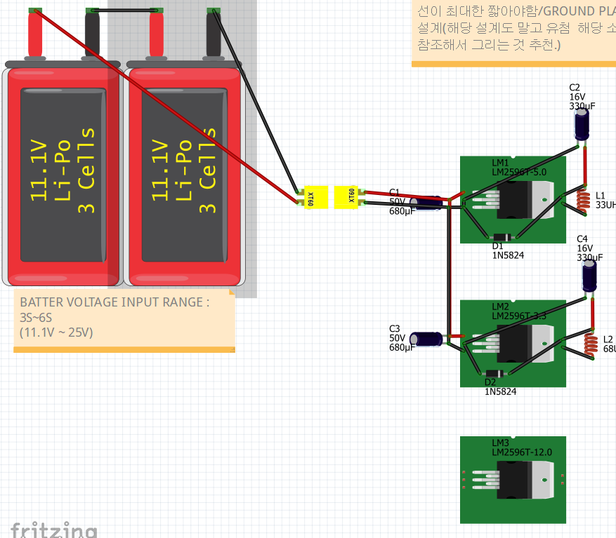
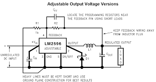
Im using LM2596 regulator and its schematic is like below :
I want to make this line up on bread-board view, but I found this is very difficult for beginner
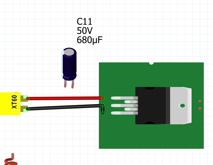
at first I tried without breadboard like below picture :
but as I connect like that, I couldn’t connect capacitor in parallel on the small PCB.
on small PCB, I could connect only one wire.(if i connect capacitor on them, I couldnt connect wire, and if i connect wire on them, i couldnt connect the capacitor.)
when i drag the wire or capacitor, i could see wires not connect properly.
when i drag the capacitor leg to connect to small PCB, it does not recognize the point.
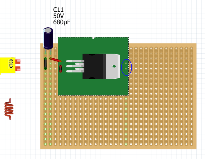
so i tried as below picture :
I used PCB strip and the problem is still exist.
when I drag 3rd pin wire and try to connect on 5th pin, i only could connect to stripboard below the voltage regulator PCB.
I should connect diode but I couldn’t and it looks very messy.
I want to connect very neatly.
I tried use bend point for connecting 3 component, but it is also failed.
below is the part file :
LM2596.fzpz (8.6 KB)
I solved problem by my own.
with schematic view, I could connect 3 wires on one point.
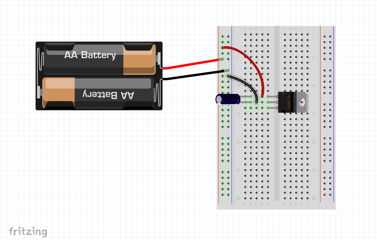
Use a solderless breadboard, you know, the thing that is in the breadboard view when you start fritzing…
The battery is connected to the two vertical columns on the left side of the breadboard. Each column has all the holes in that column connected together. This becomes your power buss. From there, I run two power wires to the center section of the breadboard. The center section has two sides. All the points in a row on one side are connected together, but not connected to the other side.
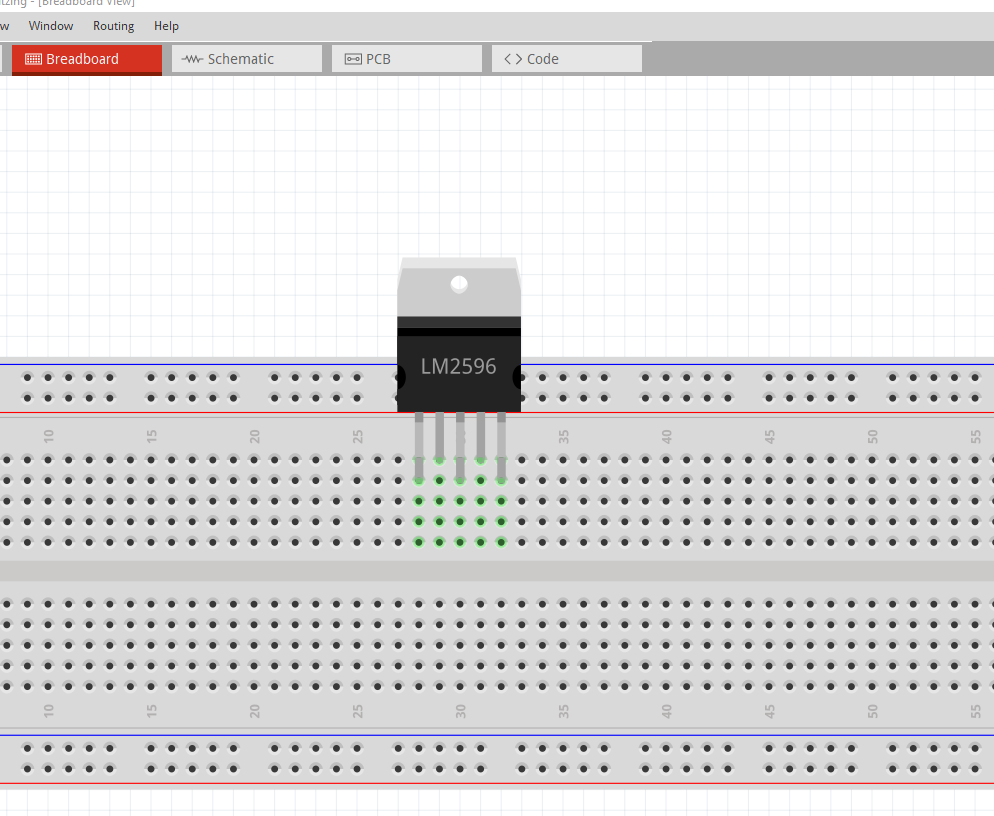
Notice how the bottom most pin of the voltage regulator isn’t connected to anything? But the row of 5 connectors is all green? That means they are all connected together. Add a wire to any open hole in that row, and it becomes connected to the bottom pin of the voltage regulator. Just like a real breadboard works in life.
In your 2nd example, every vertical column of connector holes is connected together, hence the color difference. The part you are using is not a good fritzing part, it won’t work well in fritzing. The location of all the pins should be on the same side, your part has 3 connectors on the left and two on the right, so it won’t line up correctly in fritzing.
The two pins circled are connected to the same column, so they are connected together. All green connectors in that column are connected together.
Hope this helps, and feel free to ask questions,
Randy
Thank you for your reply.
your model is LM7805, little bit different from my model.(my model have 5 legs, LM7805 have 3 legs)
so i cannot use solderless breadboard. and i already tried to use that.
thank you for your reply, and I solved the problem using schematic view.
I removed strip PCB and connected from schematic view.
Thank you for your reply!!
I somehow forgot to post this…
True, your model is different. Your model has 5 legs, but the breadboard design for that part isn’t fritzing ‘friendly’. The pin spacing of your part isn’t correct to work with a breadboard. I re-worked the breadboard .svg file to make it more fritzing like.
Now this part will work like your part and will also work on fritzing’s breadboard view.
LM2596.fzpz (8.0 KB)
Randy
Thank you!!! this model is great, I’ve never found this model before