ADDED note: The huzzah feather also starts if the leads from output pins 2 and 16 are disconnected. The LED strips flash when the reset buttons are pushed, the output pins 2 and 16 are momentarily pulled high. My guess is that it would open the transistors and cause some sort of power shortage that prevents the huzzah booting.
So my guess is that I need a capacitor somewhere to smooth this out but where?
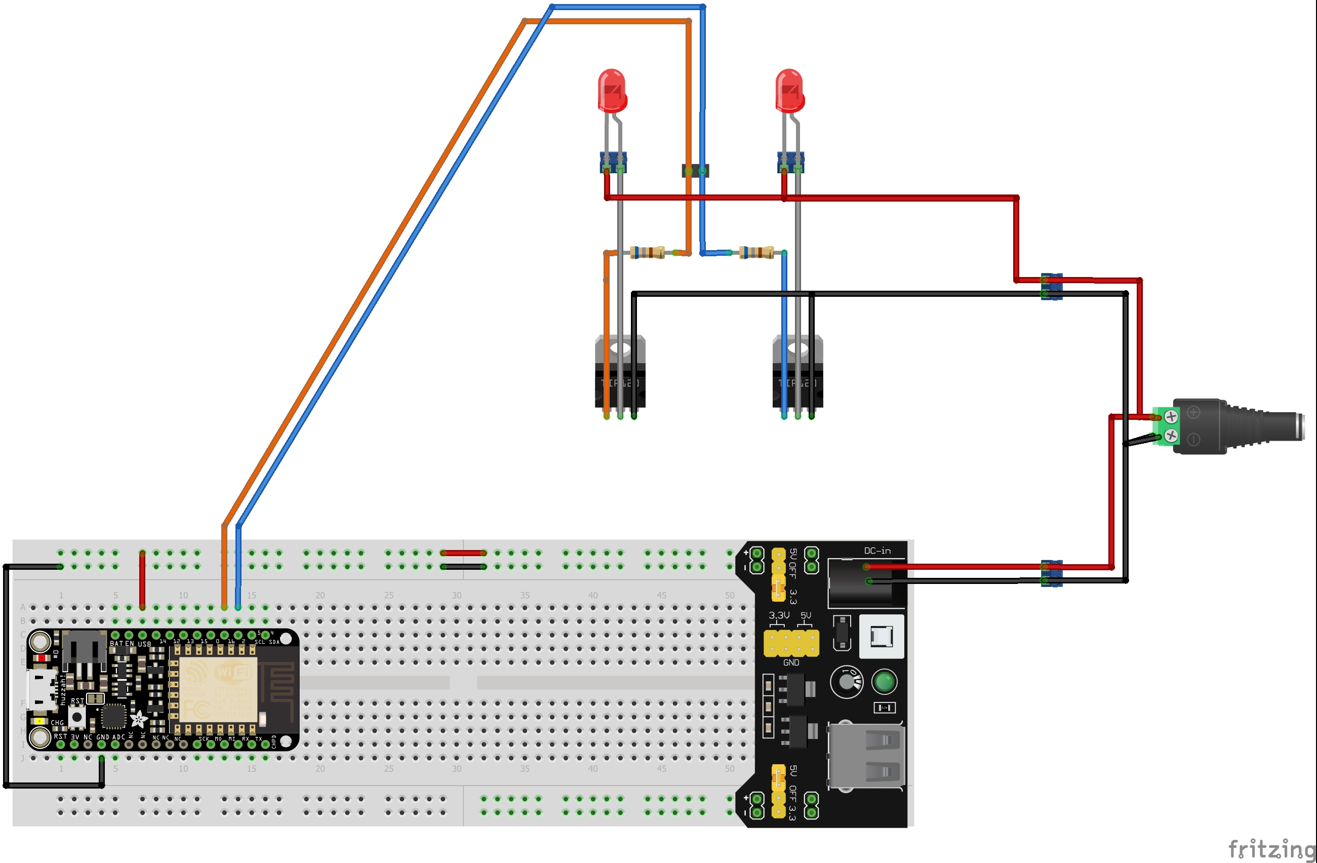
Your best bet would be to upload the fzz file of your sketch (7th icon from the left on the reply tool bar) so we can poke at the circuit. If I understand correctly the cpu resets when the leds start which likely indicates you need bypass capacitors on the power supply (or that you have a short somewhere) although I’d expect there to already be bypass caps on the CPU and the power supply which may make a short more likely. The part number for the mosfets would be useful as well since if they aren’t logic level drive (and given the feather appears to be 3.3V, possibly even if they are logic level drive) you
may need level translators to drive them properly.
Yeah I thought there would be capacitors built into the 5V regulator and the huzzah’s 3.3V regulator. If I were to put capacitors, where should they be and how big?
The Transistors are TIP122G.
If it is indeed a short, how come the whole system performs flawlessly AFTER my LED driver board is plugged in?
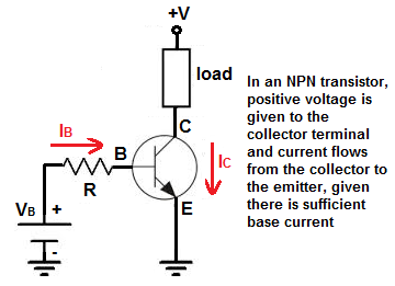
I expect your problem is your drive resistor values. Assuming you really have 68 ohm resistors there you are drawing way too much current. The huzzah can sink a max of 14ma on a port. With 68 ohm resistors you are trying to sink about 30ma,. Try replacing the two resistors with 470 ohm resistors. That gives you about 5ma of base drive to the transistors which is more than enough drive (as the transistor gain is around 2500). 1k resistors will reduce the drive to 2.5ma which also should be ample drive current for the base. I suspect drawing too much current from the output ports is causing problems during reset (and possibly may damage the output drivers). Since these are transistors not mosfets, the drive voltage isn’t an issue here 3.3v is more than enough to drive transistors
Are these some sort of fancy LEDs with a chip, because maybe they need some sort of special timing to activate.
Sorry don’t know much about actual electronics, I only watch elec videos for entertainment as most are beyond me.
OK, 680 ohms should be fine, you are well below the drive capability of the port, so likely not a driver overload.
You might try bypass capacitors (typically a .1 uf ceramic in parallel with a 10uf or so tantalum or electrolytic from ground to 3.3V as close to the micro as possible. Do the leds try and come on as soon as the program starts? If so can you try adding a delay to the software so the leds are off for a while after the micro has booted and see if that helps? If it does it indicates that there is an initial surge problem that is dropping the micro supply voltage. I’m assuming that the leds are reasonably high current due to the driver transistors. If so voltage drop from current in ground is a possible problem, but the regulated power supply connected as shown should block that from affecting the micro at most it should affect the drive to the transistors and cause the leds to not light.
edit: A late thought: check that there isn’t some limitation on the two pins you are driving the transistors with during reset. The beagle bone black cpu for instance requires that input pins be tristated (i.e. the input signals disconnected ) during reset. It is possible there is a similar restriction on your CPU that isn’t being met (although as an output it is hard to see what that restriction would be).
Not that I know of @Old_Grey, had a quick squizz at the data sheet could not find anything.
@vanepp I placed the capacitors as suggested to no avail. I think it does not work because they don’t have time to charge up or they are not big enought!
What I did discover is that if i moved the LED outputs from pins 2 and 16 to pins 0 and 16… it works!
Holding down the reset button i took the volltage from pins 0, 16 and 2(the problem pin) to ground and got:
3.1v pin 0
3.2v pin 16
3.3v pin 2
would this have anything to do with it? I would think not as @vanepp said the voltage does not matter it is the current that is amplified by a tip122g darlingotn.
SO… maybe it is the type of pin (pin 2) that is causing it? if you look at the pinout diagram for thr huzzah feather it labels pin 2 as TXD1, would this have anything to do with it?
.
.
OR
maybe it is has something to do this bit of info from the adafrui website this, found here.
I think it is more likely that bypassing isn’t your problem. If it was the bypass caps, it should also happen after boot not just at power up. As we agreed earlier the bypass caps in the power supply and the cpu should be enough
.[quote=“cafeciaojoe, post:9, topic:4579”]
What I did discover is that if i moved the LED outputs from pins 2 and 16 to pins 0 and 16… it works!
[/quote]
This seems the likely problem, for whatever reason pin 2 objects to having the transistor on it at boot and hangs the boot process somehow. If you don’t need it to be on that specific pin for some reason moving it would be a good solution. I still don’t see what it would object about having a transistor on a pin that can drive a led, but it seems a likely cause.
That is fairly normal and not a problem. The transistor base junction will always be two diode drops (about 1.2 to 1.4 volts) because it is a darlington transistor (a normal transistor is .6 to .7 volts at the base). So as long as you have more than 1.4 volts present and a sufficiently small series resistor to provide current the transistor will turn on without problem.[quote=“cafeciaojoe, post:9, topic:4579”]
maybe it is has something to do this bit of info from the adafrui website this, found here.
boot mode.PNG1129x115
[/quote]
It seems this is probably the problem (although I still don’t see why). There isn’t much information either on that page or in the full data sheet (it may depend on the firmware that is loaded) to say what “detect boot mode” means. I’d expect that if you pull it down something boot related does or doesn’t happen but it isn’t clear what. Pin 16 may also be a problem as they say it should be connected to reset (although ti also appears to be a gpio pin) as it causes wakeup from deep sleep. If you aren’t using the spi ports you may be batter to use pins 12 13 or 14 and avoid any of the boot related pins. I think what is happening is that the drive needed for the transistors is affecting the level of on the pin at boot up and causing the cpu to drop in to an unexpected mode (which is poorly documented which is unusual for Adafruit!). That would explain why it works when the leds are connected after boot occurs.
That’s probably a good bet. I expect someone there can tell you what the pin does during boot (I expect it is documented somewhere that we haven’t found yet). I’d guess that the transistor is dragging the level of the pin down and making the micro think the pin is low.
