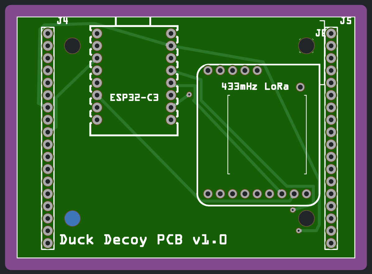
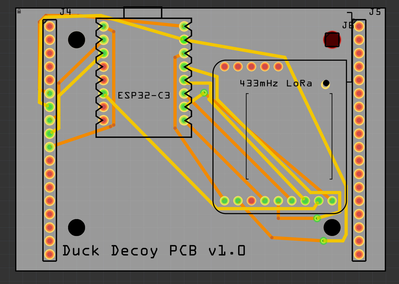
I have 4ea 3.2mm holes in my PCB design, yet when I export them to PCBWay or Aisler, the holes aren’t present. I have tried both the hole core part, as well as a through-hole from a single male pin connector. I see some of you saying the geometry has to be a perfect circle, but this is from the Fritzing parts bin so I’d assume it’s perfect?
Thanks.
Good morning,
I had a similar problem. First, I replaced ellipse with circle in the SVG text and then added the ID “nonconn”.
  <circle
     id="nonconn3"
     cx="1516.3668"
     cy="116.31814"
     fill="#000000"
     stroke="#000000"
     stroke-width="0"
     r="59.055119" />
If it was previously an ellipse, you need to convert ry and rx into r - meaning rewriting from two radii into a single radius.
Regarding the layers, I’m not entirely sure; I have the drill holes located on the copper0 layer.
Regards, Harald!
At least two of the holes look a bit wired. The one to the top right more looks like a square? And the small one seems off center from the copper ring.
Holes from the core parts indeed are taken into account by the Fab, but at least two of them don’t really look like they are core parts.
To investigate deeper, we would need the sketch (fzz file).
Duck Decoy PCB Bottom.fzz (59.3 KB)
Thank you for taking a look!