Hey ![]()
I am attempting to make a pcb for a wifi antenna ground plane, it is quite a simple thing with no components, just 2 holes, one for a bolt and one for an sma connector. I have done copper fill to cover all the 1 side of the top pcb (single sided pcb), but when i then export as gerber folder, the green solder mask layer covers right up to the edge of the holes. Please can somebody tell me how I can expose 2-4mm copper around the holes so that there is no green mask covering that section? Thanks & Best wishes
The forum posts on invisible copper (to make touch pads should do what you want. Basically you need a circle around your current circle in the copper layer of the part with a fill of none which will fool the mask layer in to not masking it but not actually create copper (because of no fill.)
Peter
which file to delete mask layer once gerber folder has been made? i think just zero green mask will do
one of
Untitled Sketch_maskTop.gts
Untitled Sketch_maskBottom.gbs
in the gerber output should delete the mask layer. Your board house may however object to there being no mask layer in the gebers so you may need to check with them. I think the invisible copper (which will leave the mask correct) is a better bet but that is up to you.
Peter
Hi there, do you happen to have a link to a tutorial or example of creating invisible copper? I still have no success in creating the simple hole with outer copper ring. Many thanks.
Sure this is the original post from 2016 there are a variety after it all based on this
(search in the forum search bar for “invisible copper” to find them all)
Peter
1 Like
ahh nice, that 12mm solder mask keepout over the hole seems to work for my needs. I wish i knew how to do it though ![]() I will read more on it now i know it is creating a custom part using svg, i need to learn more about svg layers.
I will read more on it now i know it is creating a custom part using svg, i need to learn more about svg layers.
I tried making this with a hole in a circular board which should give a mask free copper but it doesn’t work (possibly because it doesn’t have a connector to unmask the copper. I think what is likely to be easiest is if you can provide the diameter of the circle and the position and size of the two holes I can make a custom part that should work. I assume the hole in the center is for the SMA connector and thus would like to be the connector? This doesn’t really need the invisible copper hack, just a connector definition so Fritzing won’t mask the copper of the connector.
Peter
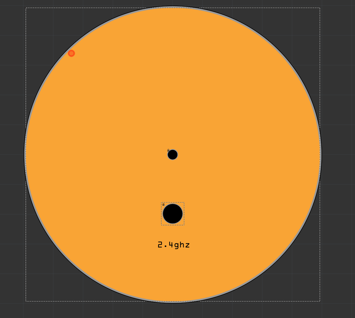
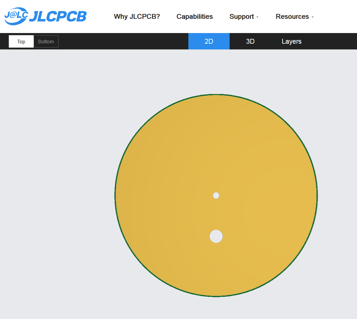
i think i found a cheat easy way, just using the center hole, in inspector, set ‘ring thickness’ to the diameter of the circle. Now when i upload the gerber to pcb company it is exposed copper, and mask is just outside edges of square which will get cut out and discarded. Fritzing gives warning of empty mask, but pcb company upload and preview looks ok. I will order a few and see if successful.
When I tried something similar, the mask was still there (as long as you are good with no mask at all which I wasn’t sure you were, just deleting the mask gerber file would also work.) Good that you found a solution.
Peter
i tried just deleting the mask layer file from the gerber output, but jlcpcb said they will fill a mask anyway, cannot have no mask file. So by making copper hole ring as big as the pcb itself, it still has mask layer, but cutout once pcb is finished. here is pcb as rectangle before cutout as circle:
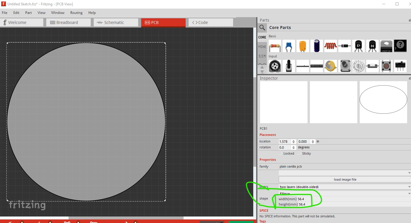
You can make the pcb a circle like this
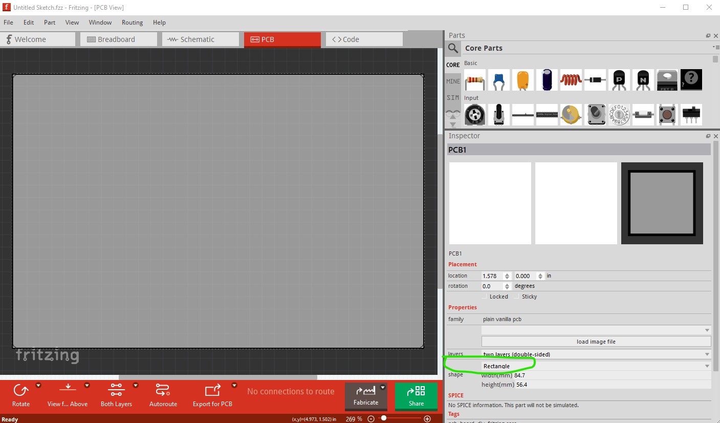
then set the height and width to whatever size you need to set the contour,gml gerber file to mill the board to a circle of the correct size.
Peter
1 Like
yep this is how i did ![]()
update, jlcpcb email a few times, they are confused by the file ![]()
"Hi there,
Sorry to bother you, but there are things that we want to confirm with you about your PCB order before proceeding.
There is no keep out layer in your file, could we use the highlight outer frame of silkscreen layer as board outline? (If there are cutouts in gerber file, please help to point out)
The circle should be in the contour.gm1 file, as far as I know that is what mills the circle.
here I did a circle and added a resistor then exported the gerbers the contour.gm1

the file displayed in gerbv
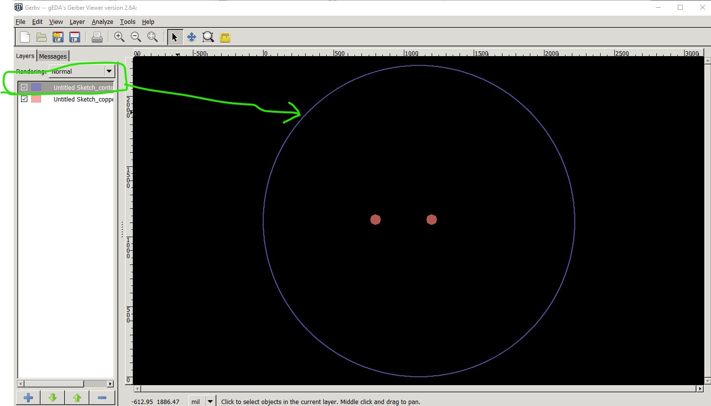
I have never actually done a board with a shape but the folks that I have helped with it have and the contour.gm1 file is where the shape is rendered.
Peter