resien encuentro esta paguina…muy buena…
Hola tengo una duda,
Ya he fabricado varias veces con fritzing, y me ha resultado todo un éxito, y creo que se ha debido a que he podido evitar crear una PCB en la que se crucen los cables. Es decir, las PCB que he diseñado salen de uno de los pines de mi Arduino Mini Pro 3.3V y van ya sea hacia una terminal donde tengo que conectar un cable de un sensor o hacia donde tengo que soldar un resistor y dicha linea sale directo del punto donde soldo la placa arduino hacia el componente (no se cruza con nada), sin embargo, tengo ahora una placa donde no he logrado idear una forma de que no tenga que pasar por un mismo punto con otra conexión.
Cuando yo presiono en un pin en fritzing, se marcan todos los pines que comparten esa conexión (y veo que todo es como yo lo deseo), pero evidentemente los cables pasan por el mismo punto.
Mi pregunta es si puedo estar tranquilo, o si es un error.
Soy nuevo en el foro me gustaría compartir mi diseño (PCB), para que alguien con más experiencia la revise a ver si está mal o no.
Gracias
If you upload the fzz file for your board (7th button from the left in the reply tool bar) we can have a look. Presumably you are doing a single sided board? If so then you likely need to use jumper wires for traces that would cross (assuming google translate managed to translate your question correctly) or switch to a double sided board which makes routing much easier.
Peter
Research templeaf.fzz (20.8 KB)
Thanks Peter,
The issue is; I would like to know if my fritzing PCB is well or not for fabrication.
There are only 5 types of connections:
SDA
SLA
VCC
GND
and
RAW
The objetive of the PCB is connect 12 MLX90614 sensors (infrared termometer), so, I need to have 12 connections of (SDA+SLA+GND+VCC), where I’ll have soldering pitch (5mm) PCB supports.
The RAW will be for battery conection, and I will have one RTC (clock) too, but this also use SDA+SLA+GND+VCC connection.
I think its pretty safe to say your board isn’t ready to produce yet. SLA is shorted to SDA and power is shorted to ground which isn’t likely to work. Anywhere you see the yellow lines copper will be present and they will happily short together if they cross each other so at present pretty much every pad is connected to every other one. There is a Fritzing part for the MLX90614 (putting MLX90614 in to the search bar on the parts bin will find it) but its pcb footprint doesn’t match your board (which may be because you are using a different version of the part). Here is an example sketch of a double sided board with 3 sensors. The darker lines are the bottom layer and the lighter the top layer. The layers can overlap each other which makes the routing easier. If you must use a single sided board then you would need to install jumpers where the traces overlap.
MLX90614.fzz (10.7 KB)
Peter
Thanks Peter
Many help is only you tell me that my PCB is not ready (thank you sincerely). This was my principal unknowing (I was not sure). Regarding the MLX90614 is not a problem, because I’m not want to put the sensor in the PCB because the sensor will be monitoring leaves at 3 meters of the PCB, so, in the PCB I have only the wires of the sensors (really pitches of 3mm for to connect the wires).
I would like to know How I can to put jumpers in the PCB to resolve the problem where the short circute are.
Thanks.
In the parts bin under pcb view (towards the bottom) second icon from the left is the jumper. It will create two pads in the pcb which are intended to be connected together by a wire between the pads. You can pull it along to make it wider than the default .1 inch if you need more space.
edit: If you don’t care about the order of the connections on the board you can do something like a line of 12 VCC connectors then a line of 12 ground connectors, and a line of 12 SDA connectors all connected together (done with .1 inch connectors here for simplicity). The sensor connects to one horizontal row of the 4 connectors as vcc gnd sda sla and avoid the jumpers entirely.
MLX90614_1.fzz (8.1 KB)
Peter
Thanks, It is a good idea, nevertheless I prefer the secuence GND+VCC+SLA+SDA, because I’ll can to see easily which wire is of each sensor, because I have other problems with the sensor (in the arduino code), and I need to build a easy form to found each sensor (each wire), because I’ll be working in the field with this.
I think with your help I found a solution for the problem (I not found the jumpers), but I think I’m not need them.
Do you have some easy form to review a PCB fritzing (for looking for mistakes?), maybe the same fritzing have one?.
I would like to review this last version.
Research templeaf.fzz (23.0 KB)
Thanks
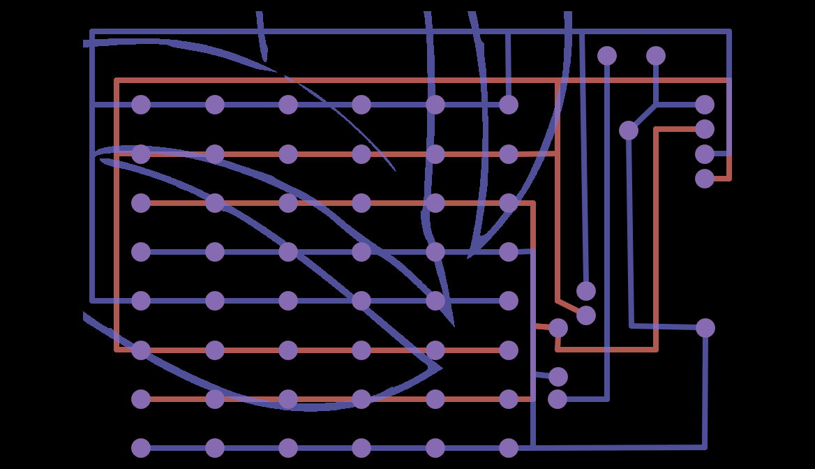
Yes I have both Fritzing and other tools (and that is fortunate because there is an error!). Your image and possibly the text are on the copper layer rather than silkscreen and thus there are shorts on the board (the DRC finds them PCB–>Routing->design rules check.) At first I didn’t see a problem but when I exported the pcb to gerbers and looked at it with gerbv the logo shows up on the bottom copper layer (scaled much too large) shorting a bunch of the pins. You also look to be missing one connection on ground. I’ll see if I can fix it up and post a corrected version in a bit.
Here is a png export from gerbv that shows the problem.Purple is the bottom copper layer and as you see your logo is there (rather than on silkscreen where it should be) and thus shorts a number of pins.
Edit:
Looks like I can’t easily change it as I don’t have the image file, so I’ll give you instructions on what you need to do: In pcb view click on your logo. In inspector (right hand bottom window) you will see img1 and the first line says copper bottom. You want to change copper bottom to Silkscreen top and then reload your image file with the load image button (for me without the image file it changes to the fritzing logo)
Note I also added a wire from the bottom layer bottom right ground connection to the grounds that go to the sensors as they were not connected before and I assume you wanted all the grounds to connect together. While I’m here I assume you are aware that you need to program all the MLX90614 sensors to have different addresses on the SMbus? If you are having software problems accessing the sensors, I’d check that, as if there are two units with the same address there will be a conflict and likely corrupted data. Below is the gerbv output of the corrected board (with the Fritzing logo rather than yours though) and the fzz file with the extra ground connector. As to that if you click on a pin in pcb view (or any other view for that matter) all the other pins that are connected to it turn yellow. That is how I verified the grounds weren’t connected together as they probably should be.
and the correct fzz:
Research templeaf3.fzz (22.7 KB)
edit2:
After a nights sleep a couple more suggestions: you likely need a resistor from the SDA line to VCC as the SMbus output is open drain and thus has no pullup (note if you have a pull up resistor on the processor driving the SMbus this isn’t necessary, but it is cheap insurance to have a space on the board for a pull up resistor, you don’t have to install it if you don’t need it, but have space to do so if you do). The other thing is that you can’t use just any of the RTC chips, you need one that supports the SMbus (and need to set its address to be different than any of the sensors). Most of the RTC parts are I2C which also uses pins called SDA and SCL but that isn’t the same as SMbus but some do appear to also support SMbus (you may already be aware of this but just in case  ). The lack of a suitable pullup resistor on the SMbus may be the cause of your software issues as well. If there isn’t sufficient pullup, sometimes communication will fail.
Peter
Thanks Peter for all your recommendations,
Regarding the logo I changed it according your instructions (I hope you can review it if you have time).
Regarding the change of direction of MLX90614 (I invested two days in this, and I learned how to resolv the problem, I learned how to change directions).
Regarding the resistences pull up (really I begin with the PCB fritzing after I prove the circuit using Arduino UNO board), so, how I get the project working I think the circuit is ready (and I not used a pull up resistence), but I would like to let provided it if I can, but I don’t know how to do that.
When I say that I have other problems with the arduino, I’m only thinking in the order of the sensors, because when I changed the direction I saw that arduino order the sensors randomly, so in the field I need to prove one by one to put them where I need (in others words, I think I do not have problem with the code).
Regarding the disconnect GND, really is not disconnected, because (maybe is imposible to see that, but I’m considering to conect a board Arduino 3.3V (so all the pins GND outside the lines of the other pins will be connected directly in the arduino 3.3V, so really them will be connected trought 3.3V PCB board. But In any case I followed your recommendation and connected all GND pins).
In this point, my only doubt is about the pull up resistance (I not sure if I need it), I proved the project but with only 4 MLX90614 sensors (I`m not have more in this moment, I bought the others 8, but I need to wait for them), I would like you can to say me how I can to provide it in the PCB fritzing. I not sure if this is only to put a resistence (to get one of the parts of fritzing) and disconnect the circuit of VCC arduino 3,3V and the others VCC pins, and if I not need this pull up, I only put a jumper in the disconnection point?
And the other thing the pull up is of 1Kohmnio?
I’m uploading 2 versions (the original with GND connection and logo corrections) and the last one with pull up prevision. Research templeaf with pull up prevision.fzz (35.6 KB)
Research templeaf.fzz (34.6 KB)
Thanks
Sorry, I had a mistake in the last PCB, this will be the correct (please review the pull down resistor, this is that you say?)Research templeaf with pull up prevision.fzz (35.9 KB)
Thanks
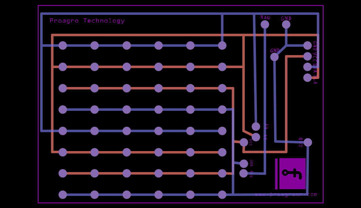
I’m happily retired so time is what I have lots of ![]() . The logo is now on silkscreen where it should be and looks fine. The scaling seemed to only affect the copper layer. The pull up resistor wasn’t wired quite right so I took your latest templeaf.fzz and made a few changes: I removed two loops (where the copper connected to itself twice as they can cause problems, there should only be one path to each pad. I added the pullup resistor and changed the routing slightly to give it some room. As noted you may not need the pull up resistor, there is a weak pull up (around 100K I think) that is selectable on the arduino, if that is on you may not need a pull up resistor on the board. With open drain outputs such as the sensors have, they pull down strongly, but when they are off do nothing (pull neither up nor down) so something else either the pull up on the arduino or the pull up resistor on the board are responsible for pulling the signal high. If there is no or not enough pullup the high signal may or may not be high enough to be recognized as a high by the arduino. Worse, it can most of the time be high enough to work but sometimes not and cause intermittent errors which are very hard to find. I’d suggest putting about a 10k resistor on the board to insure you have enough pull up. I also added labels for each of the sensor rows on the silk screen mostly so I could tell which set of pads are which when checking the connections still looked right after the changes. Here is the latest board version:
. The logo is now on silkscreen where it should be and looks fine. The scaling seemed to only affect the copper layer. The pull up resistor wasn’t wired quite right so I took your latest templeaf.fzz and made a few changes: I removed two loops (where the copper connected to itself twice as they can cause problems, there should only be one path to each pad. I added the pullup resistor and changed the routing slightly to give it some room. As noted you may not need the pull up resistor, there is a weak pull up (around 100K I think) that is selectable on the arduino, if that is on you may not need a pull up resistor on the board. With open drain outputs such as the sensors have, they pull down strongly, but when they are off do nothing (pull neither up nor down) so something else either the pull up on the arduino or the pull up resistor on the board are responsible for pulling the signal high. If there is no or not enough pullup the high signal may or may not be high enough to be recognized as a high by the arduino. Worse, it can most of the time be high enough to work but sometimes not and cause intermittent errors which are very hard to find. I’d suggest putting about a 10k resistor on the board to insure you have enough pull up. I also added labels for each of the sensor rows on the silk screen mostly so I could tell which set of pads are which when checking the connections still looked right after the changes. Here is the latest board version:
Research templeaf5.fzz (36.8 KB)
edit: about the grounds: you should try and only have one ground connection from any point (such as the arduino to the board or the board to the sensors) more than one path to the same ground point can cause problems.
Peter
Thanks,
I trying to send for manufacturing…
Are you know, why the page for manufacture changed from fritzing to Aisler? is the same? or it is a violation of fritzing page?
Aisler is the new provider of fab services for Frtizing as of a couple of months ago. The Fritzing folks have made the change so it should be fine.
Peter
Thanks Peter,
I sent it to fab, thanks very much for your help.
I have other questions, Can you explain me with a some of theory (but into the same PCB), How works the resistence 10K there.
And by the other hand, Do you know why the RTC DS3231 have two address and the RTC 24C32, have only one address.
I’m using the following arduino sketch for see that:
/*------------------------------------------------------
I2cScanner
Found in:
http://playground.arduino.cc/Main/I2cScanner
*/
#include <Wire.h>
void setup()
{
Wire.begin();
Serial.begin(9600);
Serial.println("\nI2C Scanner");
}
void loop()
{
byte error, address;
int nDevices;
Serial.println(“Scanning…”);
nDevices = 0;
for(address = 1; address < 127; address++ )
{
// The i2c_scanner uses the return value of
// the Write.endTransmisstion to see if
// a device did acknowledge to the address.
Wire.beginTransmission(address);
error = Wire.endTransmission();
if (error == 0)
{
  Serial.print("I2C device found at address 0x");
  if (address<16)
    Serial.print("0");
  Serial.print(address,HEX);
  Serial.println("  !");

  nDevices++;
}
else if (error==4)
{
  Serial.print("Unknow error at address 0x");
  if (address<16)
    Serial.print("0");
  Serial.println(address,HEX);
}
}
if (nDevices == 0)
Serial.println(“No I2C devices found\n”);
else
Serial.println(“done\n”);
delay(5000); // wait 5 seconds for next scan
}
Thanks,
This is for your many free time!
Sure. The issue is the multiple sensors on a single bus. Normally (in a non bus situation) the sensor will drive the output pin high or low (think of it as a toggle switch that switches the output pin between VCC for a high and Ground for a low. With only one sensor this works fine. However when we want to bus more than one sensor on the same bus there is a problem. If one sensor’s output is high and another sensor is low there is in effect a short between power and ground and bad things happen (probably we damage the sensors, certainly we don’t get a proper high or low signal on the bus wire because one side is trying to make it vcc and the other is making it ground. The fix to this is to disconnect the driver that connects to VCC in the sensor. So the sensor will drive the bus pin to ground when it wants to outut 0 and change to an open circuit when it wants to cause a 1 (or when it is not the sensor being addressed so it doesn’t affect the bus). The effect of this is that when the sensor is setting the bus high, nothing in the sensor is actually making the line high, it is just allowing something else (the pull up resistor) to do so. In our case we want to put the pull up resistor at the input pin to the Arduiino so that when the sensors outputs are all high (meaning they are not driving the
bus pin low) the resistor will pull the bus line close to Vcc so the Arduino sees the bus as high. Without the resistor (somewhere, either on the board or with the weak pullup on the Arduino pin enabled) a high level may not get to a high enough voltage (because nothing is driving it high) to resister as a high level on the input pin. An additional complication is that the size of the pull up resistor is determined by the maximum current (around 13ma for the temp sensors) that the sensor can pull low and the capacitance of the bus wiring (which is likely unknown) as there is a timing constraint if you are running the bus at the 400khz high speed rate. I expect there must be guidelines on the net somewhere to setting approptiate values for i2c (I seem to recall the bus length limit is something like 12 inches or so as well) so you may have to experiment with resistor values to get something that works reliably.
I think you likely have the two swapped. The 24c32 rtc should have two addresses The 24C32 isn’t an rtc, it is a serial eprom. The rtc module for a 24c32 has the 24c32 (which will be one address) and a DS1307 rtc chip (which will be the second address). The data sheet for the DS3231 says that it should have a single address at 1101000 not two as far as I can see. If I’m reading the data sheets right the address should be 101000 as the first bit is the start bit followed by 7 address bits. That would mean that none of your temp sensors can have an address of 101000 so as not to conflict with the DS3231. The addresses for the 24c32 rtc module may be fixed or set by switches on the module. If you have a choice, the DS3231 is probably better as it has a temp compensated oscillator which should keep more accurate time.
Peter
You are right, really I have a DS1307 and a DS3231, the theme is (no have problem, I think!), but it struck me that when I connect the DS3231 I have two address (0x57 and 0x58), and when I connect the DS1307 I only have one address. I’m not have problems with the address because this address are differents at the address of the sensors . I only wanted to know why I saw two address with the DS3231.
Thanks
Peter maybe you can to help me (no it so important, but if you know or is easy I would like to do it).
Is about the temperature sensor, I found in internet two arduino codes to programing the sensors MLX90614, the first one use Adafruit library, I like this code because offer two temperatures, the ambient temperature and the object temperature (by sensor). But this code not works for more of one sensor.
I found other code that works with more o one sensor, but only offer the object temperature. This is the code that I’m using because I need to get differents object temperatures at same time.
So, I would like to have two temperatures by sensor.
The specific question is, Do you know how to do for get both temperatures by sensor with the last code (code that I’m using).
I do not know much about arduino, practically all of things that I use, are really a colash of several parts, until I get that I want or I’m looking for in the same code.
Thanks.
This are the codes:
With Adafruit library
/***************************************************
This is a library example for the MLX90614 Temp Sensor
Designed specifically to work with the MLX90614 sensors in the
adafruit shop
----> https://www.adafruit.com/products/1748
----> https://www.adafruit.com/products/1749
These sensors use I2C to communicate, 2 pins are required to
interface
Adafruit invests time and resources providing this open source code,
please support Adafruit and open-source hardware by purchasing
products from Adafruit!
Written by Limor Fried/Ladyada for Adafruit Industries.
BSD license, all text above must be included in any redistribution
****************************************************/
#include <Wire.h>
#include <Adafruit_MLX90614.h>
Adafruit_MLX90614 mlx = Adafruit_MLX90614();
void setup() {
Serial.begin(9600);
Serial.println(“Adafruit MLX90614 test”);
mlx.begin();
}
void loop() {
Serial.print(“Ambient-NT = “); Serial.print(mlx.readAmbientTempC());
Serial.print(”*C\tLeaf-NT = “); Serial.print(mlx.readObjectTempC()); Serial.println(”*C”);
Serial.println();
delay(500);
}
And the other one with i2cmaster.h librery:
/**
- Dos termómetros infrarrojos MLX906114
- por Jaime Patarroyo
- basado en ‘Is it hot? Arduino + MLX90614 IR Thermometer’ por bildr.blog
- Devuelve la temperatura en Celcius y Fahrenheit de dos termómetros
- infrarrojos MLX90614, conectados a los pines TWI/I²C (en la tarjeta
- Wiring v1: 0 (SCL) y 1 (SDA) y en la tarjeta Wiring S: 8 (SCL) y 9 (SDA)).
*/
#include <Wire.h>
#include <i2cmaster.h>
int device1Address = 0x2A<<1; // 0x50 es la dirección asignada para
// comunicación I²C del sensor 1.
// Corra la dirección 1 bit a la derecha, la
// librería I²Cmaster solo necesita los 7 bits
// mas significativos para la dirección.
int device2Address = 0x34<<1; // 0x55 es la dirección asignada para
// comunicación I²C del sensor 1.
// Corra la dirección 1 bit a la derecha, la
// librería I²Cmaster solo necesita los 7 bits
// mas significativos para la dirección.
int device3Address = 0x5A<<1; // 0x55 es la dirección asignada para
// comunicación I²C del sensor 1.
// Corra la dirección 1 bit a la derecha, la
// librería I²Cmaster solo necesita los 7 bits
// mas significativos para la dirección.
int device4Address = 0x74<<1; // 0x55 es la dirección asignada para
// comunicación I²C del sensor 1.
// Corra la dirección 1 bit a la derecha, la
// librería I²Cmaster solo necesita los 7 bits
// mas significativos para la dirección.
//Adafruit_MLX90614 mlx = Adafruit_MLX90614();
float celcius1 = 0; // Variable que contiene la temperatura en Celcius
// para el sensor 1.
float celcius2 = 0; // Variable que contiene la temperatura en Celcius
// para el sensor 2.
float celcius3 = 0; // Variable que contiene la temperatura en Celcius
// para el sensor 3.
float celcius4 = 0; // Variable que contiene la temperatura en Celcius
// para el sensor 4.
void setup()
{
Serial.begin(9600); // Inicia la comunicación serial a 9600bps.
i2c_init(); // Inicia el bus i2c.
PORTC = (1 << PORTC4) | (1 << PORTC5); // Habilita ‘pullups’.
}
void loop()
{
celcius1 = temperatureCelcius(device1Address);// Lee los datos del MLX90614
celcius2 = temperatureCelcius(device2Address);// con la dirección dada,
celcius3 = temperatureCelcius(device3Address); // los transforma en
celcius4 = temperatureCelcius(device4Address); // temperatura en Celcius y
// la guarda en las variables
// celcius1 o celcius2.
Serial.print(celcius1); // el puerto serial.
Serial.print(" “);
Serial.print(celcius2);
Serial.print(” “);
Serial.print(celcius3);
Serial.print(” ");
Serial.println(celcius4);
delay(1000); // Espera un segundo para imprimir de nuevo.
}
float temperatureCelcius(int address) {
int dev = address;
int data_low = 0;
int data_high = 0;
int pec = 0;
// Escribe
i2c_start_wait(dev+I2C_WRITE);
i2c_write(0x07);
// Lee
i2c_rep_start(dev+I2C_READ);
data_low = i2c_readAck(); // Lee 1 byte y envía ack.
data_high = i2c_readAck(); // Lee 1 byte y envía ack
pec = i2c_readNak();
i2c_stop();
// Esto convierte los bytes altos y bajos juntos y procesa la temperatura.
double tempFactor = 0.02; // 0.02 grados por LSB (medida de
// resolución del MLX90614).
double tempData = 0x0000;
int frac; // Datos después del punto decimal.
// Esto oculta el error del byte alto y lo mueve a la izquierda
// 8 bits y agrega el byte bajo.
tempData = (double)(((data_high & 0x007F) << 8) + data_low);
tempData = (tempData * tempFactor)-0.01;
float celcius = tempData - 273.15;
// Retorna la temperatura en Celcius.
return celcius;
}
I must not have explained clearly enough. I think you have it backwards. I think you have two addresses with the DS1307 One address talks the rtc chip (the DS1307) and the other address talks to the serial eprom chip the 24c32 which provides some number of bytes of storage which I expect you aren’t using. There are two addresses because there are two different chips on the board. The DS3231 is more likely the single address device with only the DS3231 on it (no extra storage and thus no need for the second address).
As to your code question I think it is as easy as just adding the address information to the adafruit library call.
so here in the adafruit code
mlx.begin();
}
void loop() {
add this:
mlx.begin();
}
int device1Address = 0x2A<<1; // 0x50 es la dirección asignada para
// comunicación I²C del sensor 1.
// Corra la dirección 1 bit a la derecha, la
// librería I²Cmaster solo necesita los 7 bits
// mas significativos para la dirección.
int device2Address = 0x34<<1; // 0x55 es la dirección asignada para
// comunicación I²C del sensor 1.
// Corra la dirección 1 bit a la derecha, la
// librería I²Cmaster solo necesita los 7 bits
// mas significativos para la dirección.
int device3Address = 0x5A<<1; // 0x55 es la dirección asignada para
// comunicación I²C del sensor 1.
// Corra la dirección 1 bit a la derecha, la
// librería I²Cmaster solo necesita los 7 bits
// mas significativos para la dirección.
int device4Address = 0x74<<1; // 0x55 es la dirección asignada para
// comunicación I²C del sensor 1.
// Corra la dirección 1 bit a la derecha, la
// librería I²Cmaster solo necesita los 7 bits
// mas significativos para la dirección.
void loop() {
Serial.print("Ambient-NT = "); Serial.print(mlx.readAmbientTempC(device1Address));
Serial.print("C\tLeaf-NT = "); Serial.print(mlx.readObjectTempC(device1Address)); Serial.println(“C”);
Serial.print("Ambient-NT = "); Serial.print(mlx.readAmbientTempC(device2Address));
Serial.print("C\tLeaf-NT = "); Serial.print(mlx.readObjectTempC(device2Address)); Serial.println(“C”);
Serial.print("Ambient-NT = "); Serial.print(mlx.readAmbientTempC(device3Address));
Serial.print("C\tLeaf-NT = "); Serial.print(mlx.readObjectTempC(device3Address)); Serial.println(“C”);
Serial.print("Ambient-NT = "); Serial.print(mlx.readAmbientTempC(device4Address));
Serial.print("C\tLeaf-NT = "); Serial.print(mlx.readObjectTempC(device4Address)); Serial.println(“C”);
Serial.println();
delay(500);
}
basically the change is to add the address as a parameter to the library call. At present (with the () ) it is using the default address for the sensor set in the library. It may complain about the int device1Address as being a type mismatch in which case try replacing the int with uint8_t which is what the library is expecting.
Peter
Thank you Peter,
I will test the code when I recover the sensors, since I am preparing them for the outdoor with durethan (I hope I am not committing arduinocide!), I am putting durethan to welds of the MLX90614, because I need them to use outdoor.
This is Durethan:
https://techcenter.lanxess.com/scp/americas/en/products/description/47/index.jsp?pid=47
As for the two directions of the DS3231, it is on the DS3231 (I’m sure), but I will try again, maybe it was just trash what came out, and I removed it and I connected the DS1307 and appeared only one direction and I caught my attention and for that I asked you, but it was not something I struggled with. I will review it again.
Thanks