It is likely that you have shorted power to ground either in breadboard or in another view. If you upload the sketch (the .fzz file, upload is 7th icon from the left in the reply menu) one of us will look at it and point out the error.
Peter
via google translate:
Es probable que haya un cortocircuito en la alimentación a tierra en la placa de pruebas o en otra vista. Si carga el boceto (el archivo .fzz, la carga es el séptimo ícono de la izquierda en el menú de respuesta), uno de nosotros lo revisará y señalará el error.
Error fritzing1.fzz (28.5 KB)
There is… Thanks <3
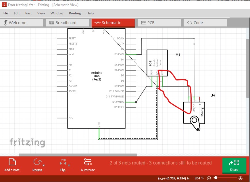
You have shorted 5V to ground in schematic (the red circled connection)
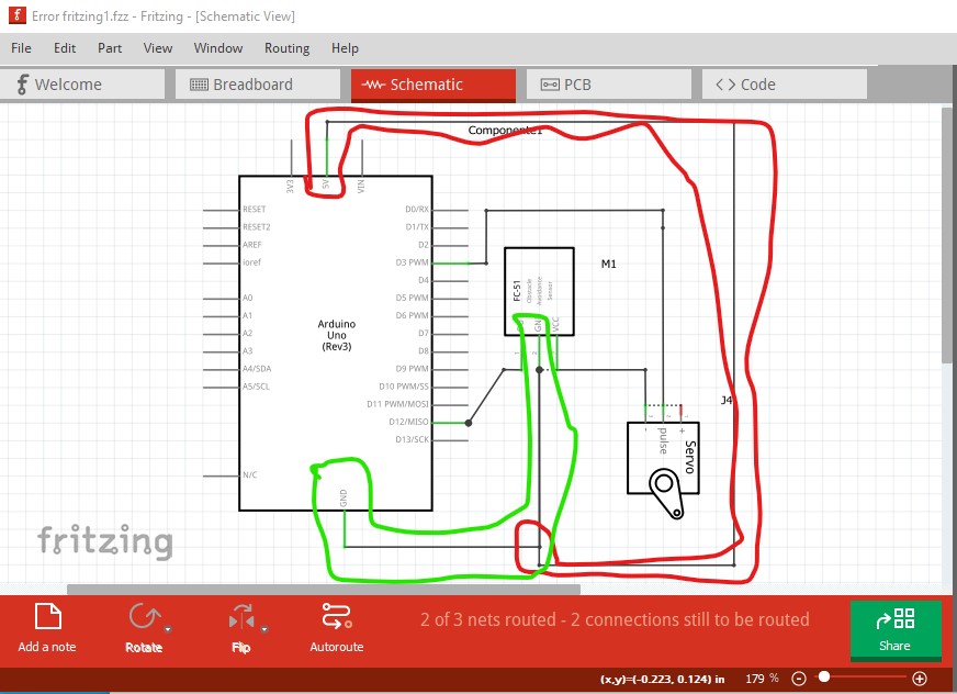
That then reflects back in to breadboard as a rats nest line. The same error is also in pcb so just fixing schematic doesn’t cure it.
here I moved the cursor over the pin on the servo in schematic which brings up the pin name (VCC) which connects to ground on the Arduino which is incorrect.
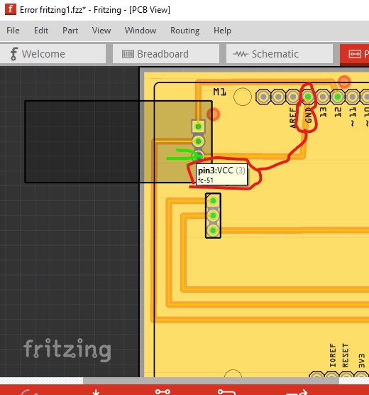
Then the VCC pin from the fc-51 connects to ground on the servo which is also incorrect (and likely exists in pcb as well which will leave the problem even when schematic is fixed!)
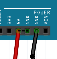
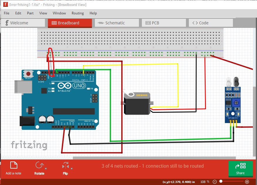
as well there is a missing ground wire in breadboard (which is present correctly in pcb and thus appears as a rats nest line) circled in red here
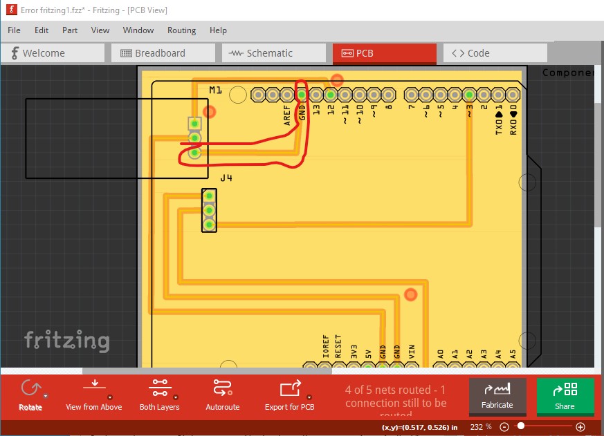
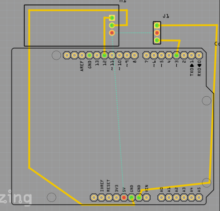
Here in pcb I deleted the incorrect trace (circled in red) and it now shows the rats nest line to the correct connection circled in green)
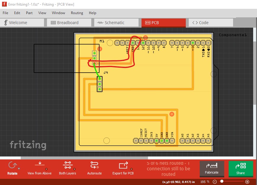
which needs to be routed then the ground fill done again. In schematic I deleted the wires that are incorrect which leaves the correct connections as rats nest lines. If you click and drag on a rats nest line it will form the wire and you can then move the wire to route it correctly. The correct wires for VCC are shown in red and the one for ground in black in this image.

adding the missing ground in breadboard and deleting the ground fill in pcb, rerouting the trace (again click and drag on the rats nest line will make the proper connection that you can then drag around is easiest) then redo the ground fill and all should be well.
Peter
vai google translate:
Ha hecho un cortocircuito de 5 V a tierra en el esquema (la conexión con un círculo rojo)
Eso luego se refleja en la placa de pruebas como una línea de nido de ratas. El mismo error también está en pcb, por lo que solo arreglar el esquema no lo cura.
aquí moví el cursor sobre el pin en el servo en el esquema que muestra el nombre del pin (VCC) que se conecta a tierra en el Arduino, lo cual es incorrecto.
Luego, el pin VCC del fc-51 se conecta a tierra en el servo, lo que también es incorrecto (y probablemente también exista en la PCB, lo que dejará el problema incluso cuando el esquema esté arreglado).
Además, falta un cable de tierra en la placa de pruebas (que está presente correctamente en la placa de circuito impreso y, por lo tanto, aparece como una línea de nido de ratas) con un círculo rojo aquí.
Aquí, en pcb, eliminé el rastro incorrecto (encerrado en un círculo en rojo) y ahora muestra la línea del nido de ratas a la conexión correcta en un círculo en verde)
que debe enrutarse, luego el relleno del suelo se hace nuevamente. En el esquema, eliminé los cables que son incorrectos, lo que deja las conexiones correctas a medida que las ratas anidan las líneas. Si hace clic y arrastra sobre una línea de nido de ratas, se formará el cable y luego podrá mover el cable para enrutarlo correctamente. Los cables correctos para VCC se muestran en rojo y el de tierra en negro en esta imagen.
agregando el terreno faltante en la placa de pruebas y eliminando el relleno de tierra en la pcb, reencaminando el trazado (nuevamente, haga clic y arrastre en la línea del nido de ratas hará que la conexión adecuada que luego puede arrastrar es más fácil) luego rehaga el relleno de terreno y todo debería ser bien.
Ok, i deleted the wrong wires, but now it shows me a connection between the vvc of servo, vcc of the sensor and the 5V, i don´t know if thats right… (sorry bad english) .-.
Yes that should be correct. VCC on the sensor and the servo should go to 5V on the Arduino.
Peter