I am hoping someone here can help me convert this schematic to a clean breadboard view? When I switch to breadboard some of the parts don’t line up and I am struggling with how to build on my board. I am fairly new to fritzing and schematics. I sort understand what is going with the schematic but it would help me greatly if someone might clean up the breadboard view for me a little. Thank you for any help you can give.
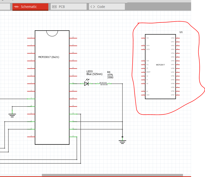
Welcome aboard! First thing I would suggest is perhaps swapping the current mcp23017 part with the one from here:
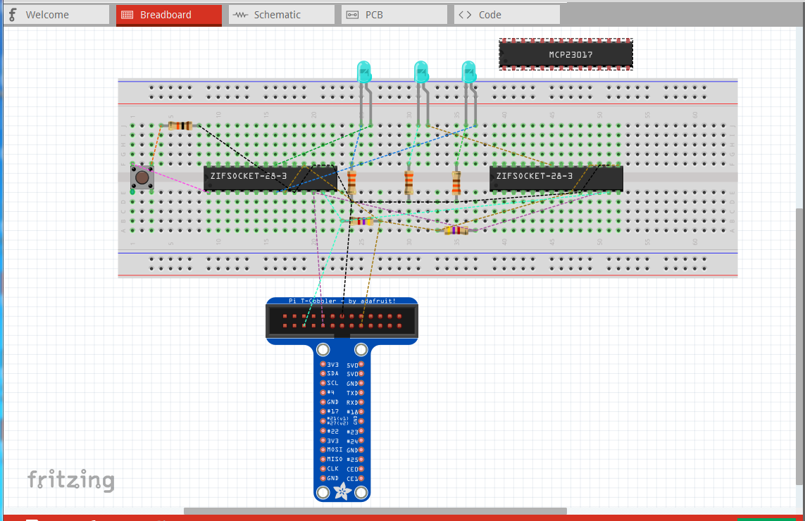
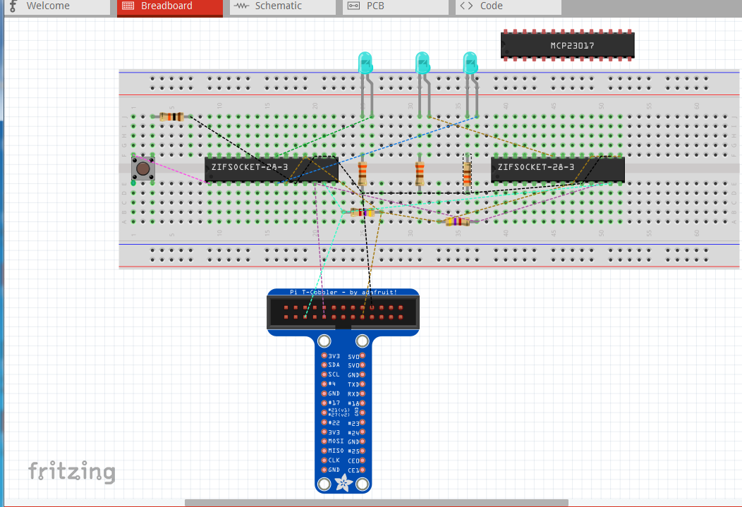
because it has pin labels in schematic and appears as the mcp23017 in breadboard (rather than a zif socket) unless the zip socket is intended. Next you need to move the components in breadboard to sensible locations (Fritzing by default loads parts on top of each other which can be confusing) here, I have moved them so each component is independent of any other (not the optimal way to do this) so the rats nest lines (the colored dotted lines) all appear. The rats nest lines reflect the connections in schematic and will become wires when clicked on. You have done the best practice of completing one view completely (in this case schematic) and now need to use the rats nest lines to make the connections in breadboard (and pcb if you want pcb as well.):
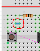
note I needed to rotate (right click on the part and click rotate) several of the parts to get the rats nest lines to route correctly. Now I will move some of the parts to pre make the connections (which will remove some of the rats nest lines) I could also just connect the two breadboard rows with a wire like this:
the wire (circled in red) has made the connection and removed the rats nest line, but is in efficient. A better choice is moving the resistor one position left to make the connection directly which is done here (for everything it can be done for. the top 4 resistors.) Note the rats nest lines for one pin of the four resistors is now gone:
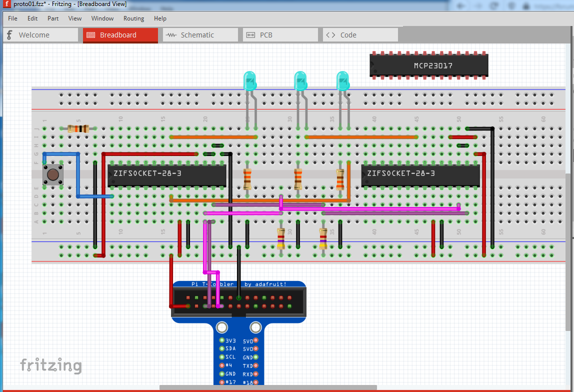
In the end I added buses for gnd and 3.3v on the bottom power rails, and rotated the pull up resistors for scl and sda to connect to the power buses to create this fully routed breadboard. Note that I set View->set grid size from .1in down to .05in so that the wires can be routed between two pins in order to make it clear which connector on the T-cobbler is connected. You don’t have to do this but I find it easier to read. I also added (but didn’t connect) the referenced mcp23017 part to show the differences:
Thank you so much! This so helpful, especially with everything going on at the moment in the world. Gives me something to work on while I am trying to stay indoors except for going to work.