Hi,
I’m completely new to new to circuits and breadboards. I have been studying and trying my best. And I’m loving it!
I have spent more time than I on building a magnetic stirrer and the circuit to put it together. I just downloaded the fritzing software and I think is fantastic.
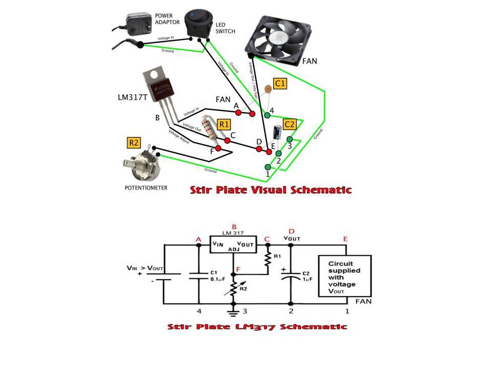
I have the schematic diagram and the “visual” diagram of what I need, but, I haven’t been able to put it together into a breadboard.
These images are taken from https://biohazardbrewery.wordpress.com/instruments/brewery-stirplate/
I would like to know if someone have enough time for putting this project together so I could have an idea of how it would look like into a breadboard and then I will struggle with the PCB to actually build it. Right now I just want to put together the breadboard.
I know the schematic design does not include the on/off switch and I would like to ask you guys if you could add it to the diagram.
I haven’t found anything like a fan on the database but I know you can add it.
If any of you guys could take the time to build this in fritzing I will seriously appreciate it. THX!
The characteristic of the components are the following:
• C1- Ceramic Capacitor 0.1µF rated for 25V but I have one rated for 50V
• C2- Electrolytic Capacitor 1µF rated for 25V but I have one rated for 50V
• LM317T
• R1- 120Ω ¼ W
• R2- 1kΩ 5W potentiometer
• Fan- 12VDC .15amp
Please let me know if you guys see something weird or off in this since you are the experts.
Thank you so much guys.
