
trying to create board from this svg laser cut trace but cant seem to get it to fill. can anyone help me out. i brought into inkscape but fill operations fail.
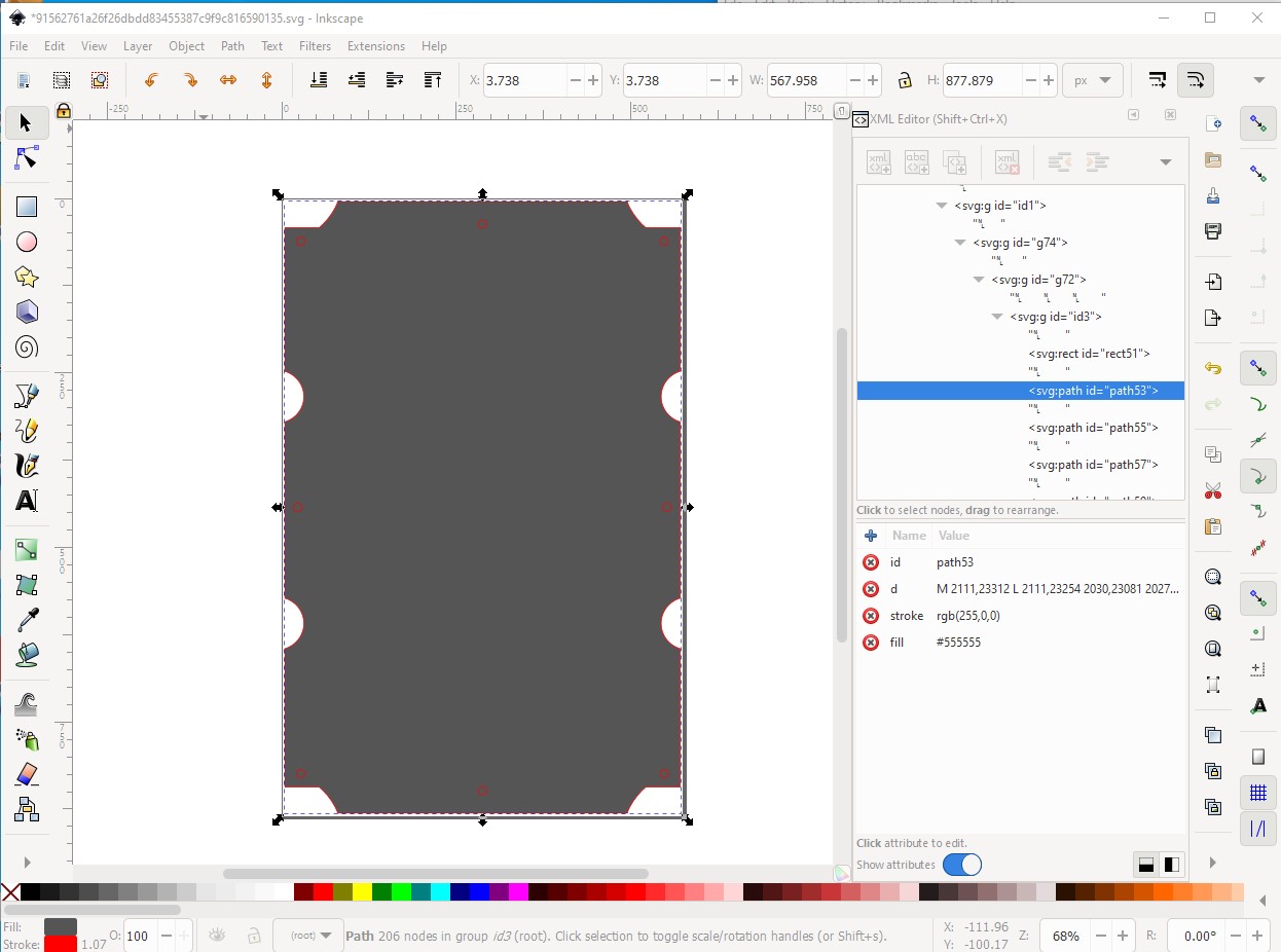
Works for me. Load the svg in to Inkscape:

select the path, then change the fill attribute with xml editor from none to #555555 (grey) and the fill takes.
You probably want to ungroup it for use with Fritzing. I assume you want to make this breadbord and perhaps pcb?
Peter
Is there a way to keep the holes ?
Yep, the holes are still there they may be at lower level than the path and thus obscured though.
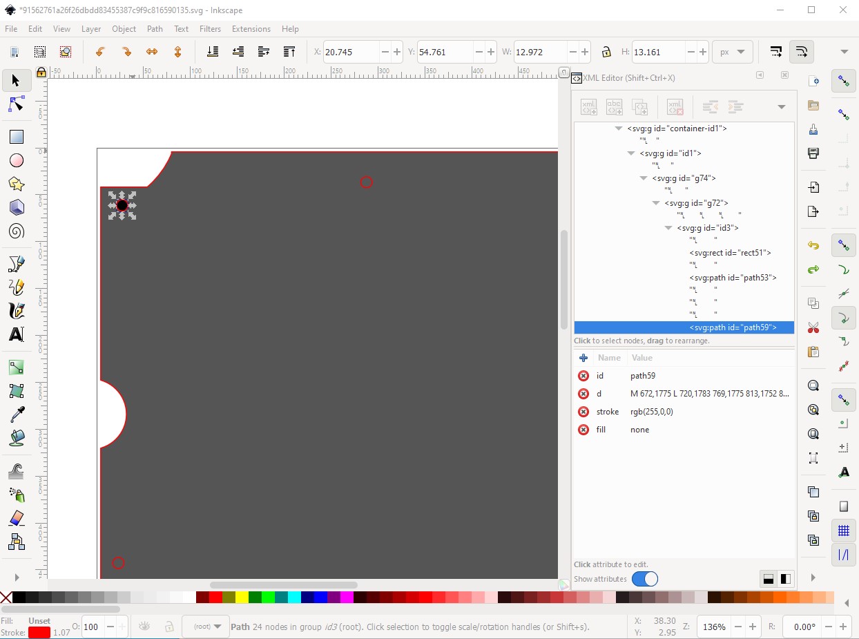
to make it more visible I changed the fill to white (#ffffff):
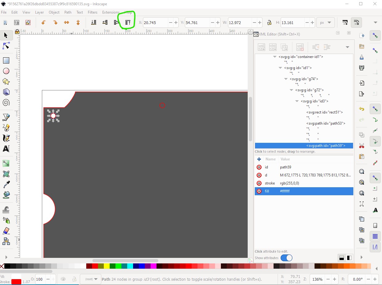
if it is obscured you can use the raise lower buttons on the tool bar (circled in green in the image) to move the element up or down in relation to the path to make it visible or invisible.
Peter
Perhaps this is what you meant. This is now a single path with the holes cut out of it. I used the Inkscape differences tool to create this, and deleted all of the extra groups and defs from openoffice/staroffice. This is now “just” the path.

this is the pcb shape im trying to get to but when i bring into inkscape and change the silkscreen layer to no fill ect i dont even get an outline. any help please i have been watching videos but in just not getting it?
The path that I created is really intended to be use as the board itself. If you want to use it for silk screen, you need to set fill to “none” (what you did), plus set the stroke to black and set a stroke width. Here is the previous svg with those changes, with stroke-width set to 50. That needs adjusting to get the thickness you want.

For silkscreen, it is not necessary to ‘get fancy’ with the path and cutout like this. Any graphics with stroke (colour and width), without fill should work. The stroke colour should be black.
thanks . i had a problem with the labels ids ect. i finally just fixe it and it exports properly now. thanks for the help.