Hi newbie here.
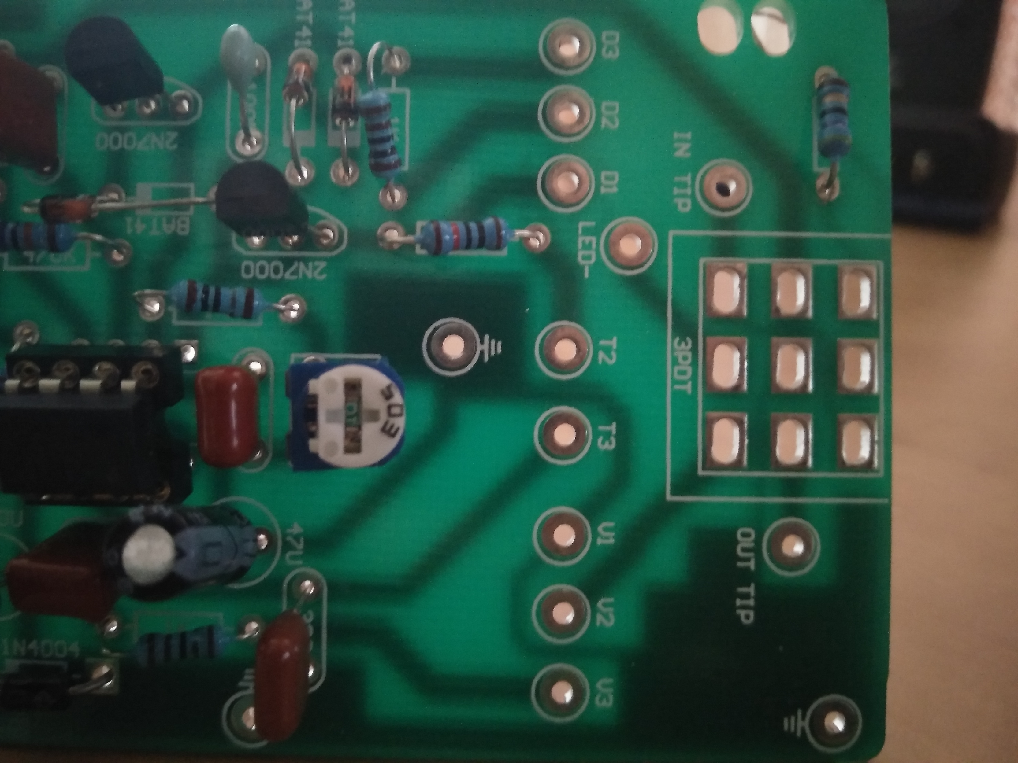
What would be the best way to recreate the " IN TIP" and “OUT TIP” holes on this pcb in the pcb view?
This is from a guitar pedal kit btw.
I saw an option for holes but i think they are just holes for mounting screws.
1 Like
That is correct, the hole option is just a hole, no copper pad. Assuming you want to connect a wire (as opposed to a component of some kind) to your hole, a connector out of core parts set to 1 pin via inspector should do what you want. It will create a pad in pcb with a .039 (suitable for a .1 connector or a piece of wire) hole and a surrounding copper pad which you can route traces to in pcb and appear as a connector in schematic and breadboard view. A via is also an option but the hole is much smaller and may not have enough room for a wire.
Peter
1 Like
I would just use a Generic Female Header set to one pin and with the part silkscreen hidden.
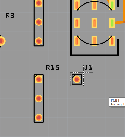
I got this J1 connector from what you said. I think it will work perfectly for what i need. Thanks!
i also saw the via option and it seemed small.
A via is a plated through hole with a pad on both sides of the board, and you change sizes in the Inspector.
Maybe you should watch some Fritzing tutorials to pick up more tips, because it has lots of hidden things.