Hi, I’m fairly new to electronics so I appreciate any help I can get.
I’m trying to design a circuit that can provide a constant current of about 50 microamperes (μA) to the anode, using a 1.5V battery.
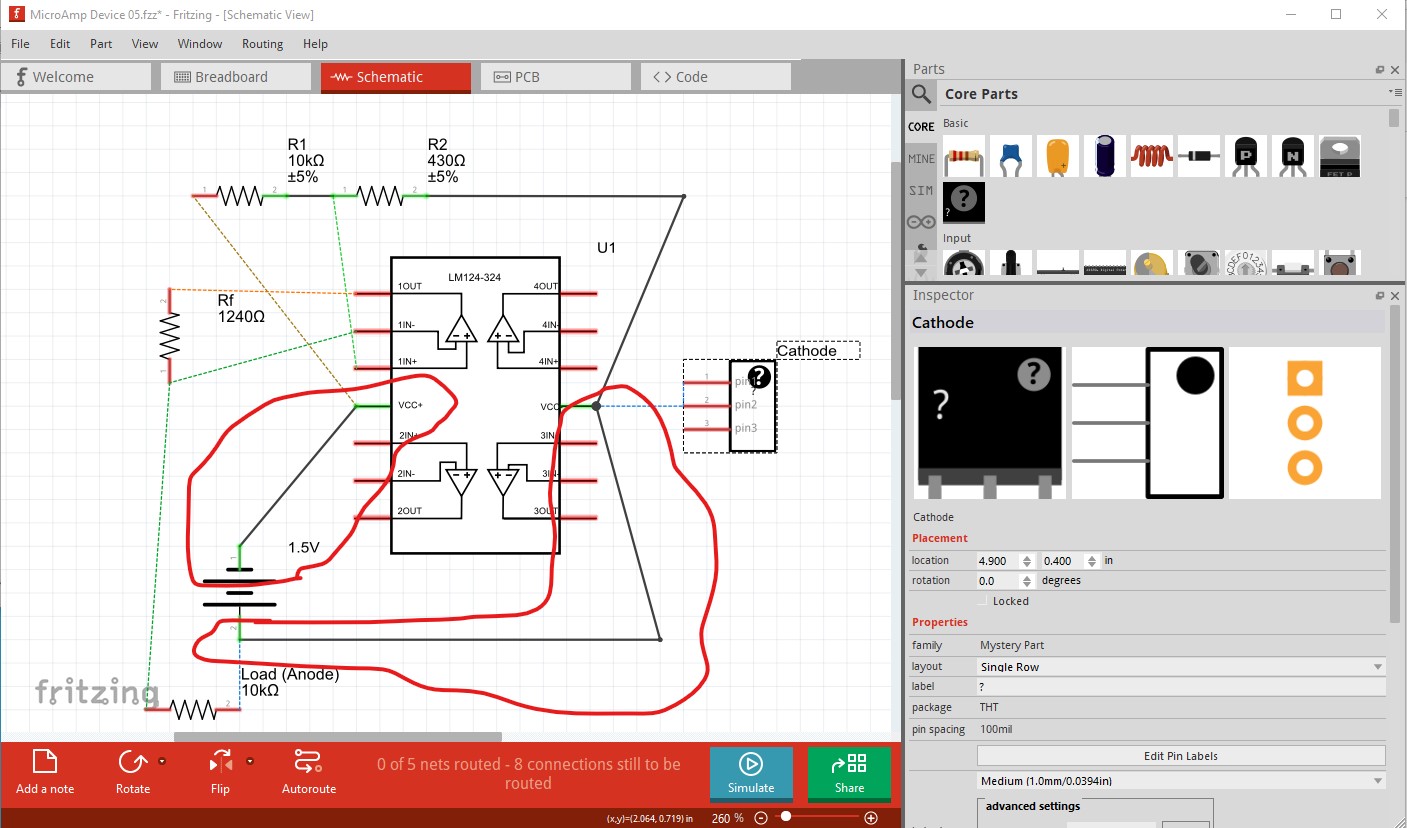
I was trying to test it in the simulator with a Multimeter, but I think I’m not doing it correctly, only getting Err. I’m also not sure if I placed the cathode correctly in the design.
I uploaded the design in case someone can check it out.
For starters your battery is hooked up backwards (which is likely to destroy the op amp!) Pin 4 should be the positive pin of the battery not the negative.
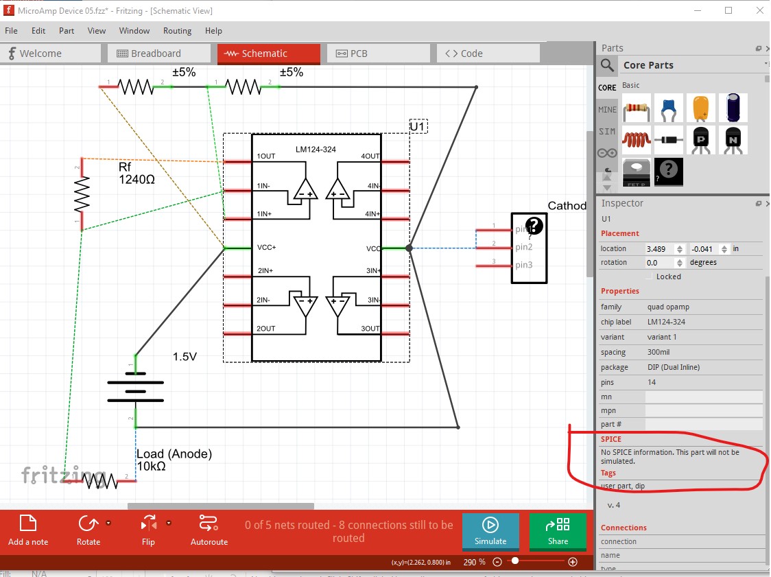
It is unclear what the mystery part is supposed to be or do, it currently doesn’t connect to anything. As a result there isn’ t much to say about this circuit.
edit:
As well the lm324 does not have spice data in the part and thus won’t be simulated, so the simulation is unlikely to actually work even if the circuit is corrected.
Thank you very much Peter, that was very helpful. Good thing I asked before I hooked it up. Between the anode and the cathode should be a poorly healing wound, such as a diabetic ulcer. I’m a physician, not an electronics engineer, so I really appreciate the help.
Will that design get me the 50 microamps continually? If I build it on a breadboard, how should I place the multimeter to test it?
First thing to note is actually using this on someone could be dangerous. Biomedical devices are highly regulated for good reason (and come with high liability!) I don’t think the circuit as it stands will work, the op amp has a negative gain and would likely be unstable and what I think is intended to be the load isn’t attached to the output of the op amp (which it needs to be to regulate the current.) A quick google search for “op amp constant current source” turns up this article describing options,
but for a medical device (or anything intended to be attached to a human) you really need an engineer familiar with biomedical devices and the needed approvals. As noted applying current to humans is a dangerous pastime where if you make a mistake death (and the attached liability) is a real possibility. While I would say that is unlikely with a 1.5V battery, I don’t know that it is impossible either and I wouldn’t try it. I think you would be better off finding an existing medical device that is approved to do something like this (assuming of course that there is such a device!)
This is more of a thought experiment at the moment. Not even in phase I trials. As far as I know there is no such medical device commercially available. A 1.5v battery can’t cause harm in it’s intended use in this design. TENS units work at far higher currents and are considered safe. Patients with epilepsy and pacemakers/arrythmias would of course be excluded, as a precautionary measure.
Thanks for the article. Which one of the designs discussed would you recommend?
I’d probably go with one of the op amp versions rather than a power supply chip. The op amp is more likely to be able to deal with the small current involved (power supply chips are optimized for high currents and may have problems with currents in the Ua range.) The LM324 (in the first data sheet I saw) seems to have a minimum supply voltage of 3V so you would need at least 3V to run it (the output voltage can be less than that though.) Skin resistance (which I believe is quite high) will also have an effect and may require a much higher (and thus potentially dangerous) voltage than 1.5 or 3V to get 50ua flowing. An ohmmeter applied to the skin at the expected distance may give a value for skin resistance and from there ohms law (I = E * R) will give you the voltage needed to source the source the desired current. A current limiting circuit that won’t allow more than the specified amount of current would also be a good bet (that could be as simple as a series resistor which won’t pass more than 50 microamps at the maximum available voltage.) You need to be designing in a fail safe manner (i.e. even an unexpected component failure can’t cause damage.)
Thanks again Peter. I’m basing this design off patent US5814094A (US5814094A - Iontopheretic system for stimulation of tissue healing and regeneration - Google Patents). It’s a very interesting read, I hope you can take a look at it. I’ve never seen anything else like it. The research stalled after the DoD stopped funding. Let’s just say that the researcher discovered some inconvenient facts that the military disliked.
I’m looking at a current pump design. I read that the LM324 can work at lower supply voltages and the 1.5V battery shouldn’t be a problem. But I’ll change the op amp if necessary of course.
Skin resistance is highly variable, that’s why I’m looking at this type of configuration. The situation can be helped using conducting gels, but I was planning on using an ohm meter to test it out. The device is to be worn for longer periods of time (72h+), so it could be the case that a close enough average for the skin resistance could work.
Was definitely planning on designing in a fail safe manner. I want to first get the most basic aspects running.
Thanks for all your input, you’ve been very generous with your time.
The variable skin resistance makes a constant current source a good idea, but what I expect (but don’t really know) to be high resistances also generate noise problems making the analog design more difficult. You are dealing with very low currents and presumably high resistances (which make external noise sources more significant) so the design is likely to be fairly complex. It is likely possible to do, but you need someone with a lot of experience in analog circuit design and I don’t think they are all that common (I know I’m not good enough for something like this!) The potentially high resistances may mean that you need more voltage than 1.5 volts to generate the needed current and as noted, external noise sources may make getting the current correct at the electrodes difficult. Good luck!
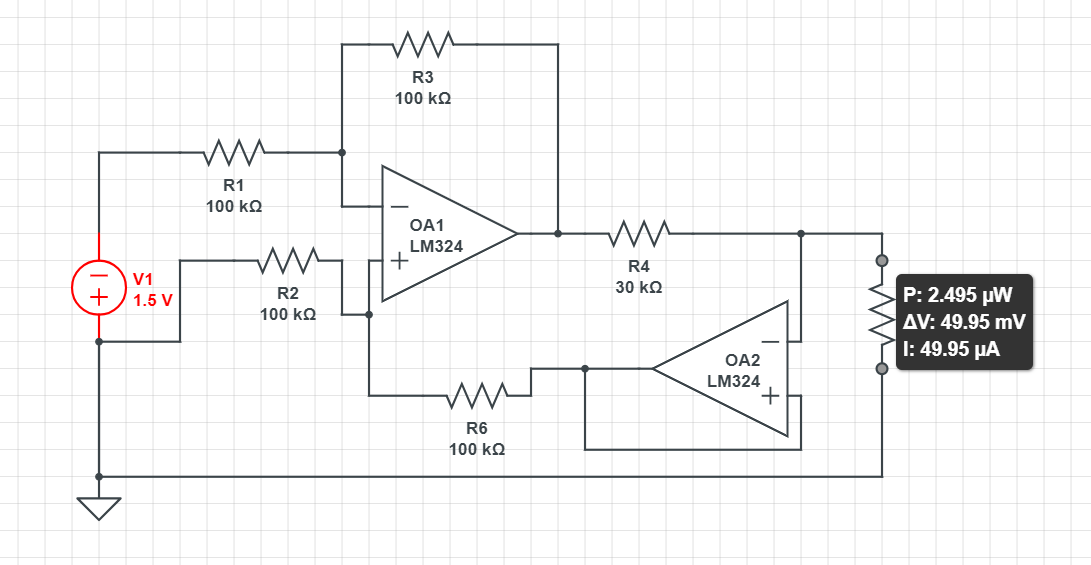
I’m trying one of the current pump designs you showed me in CircuitLab. This seems to work and does provide 50uA as desired (and it provides the same current regardless if I put 1000 ohm as skin resistance or 100,000 ohm).
I wanted to provide an update. I got the circuit running with the above design. Ended up using 2.4v (two AA rechargeable batteries). I tested it on a dummy load for 6 hours and it performed as intended. Thanks to everyone for the comments and help.