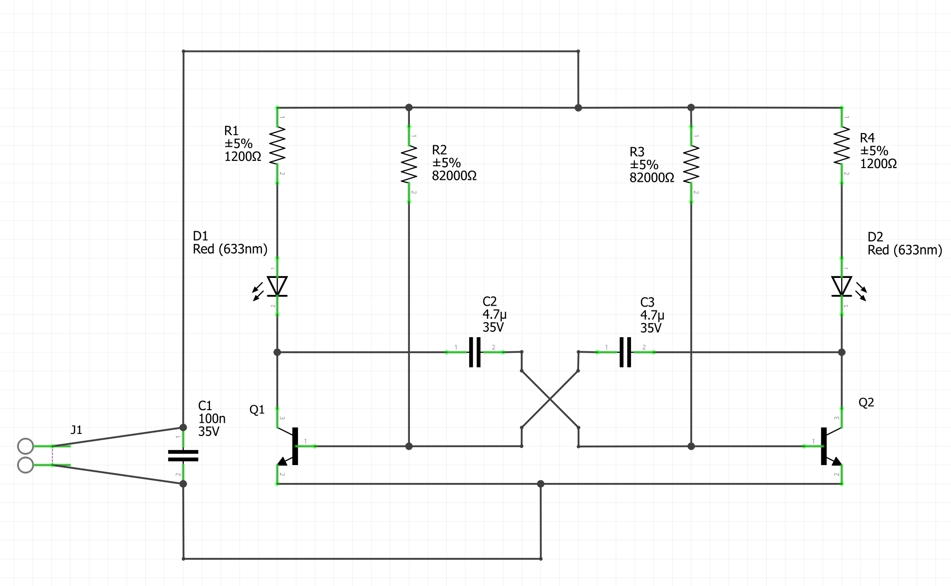
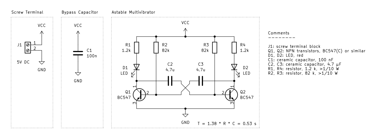
In my assignment, I have to implement an astable multivibrator (image1).
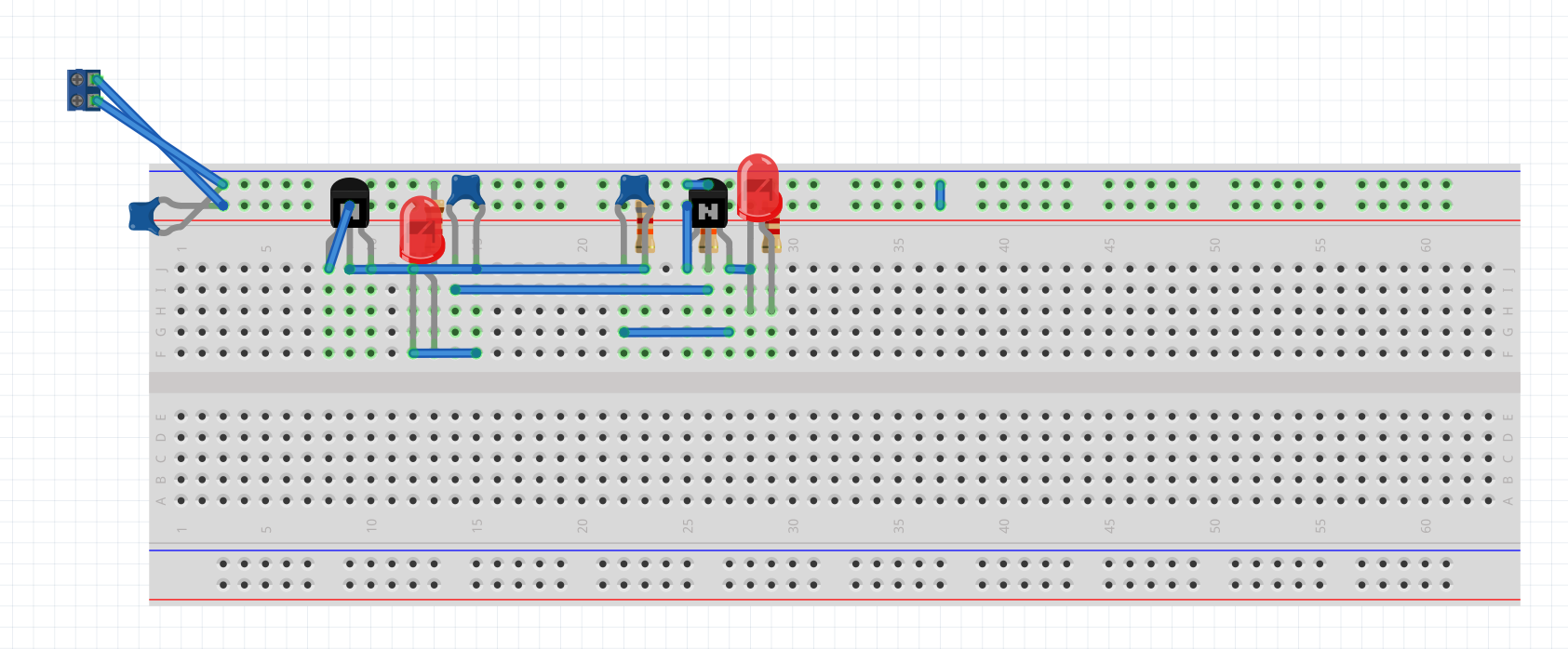
I am a total beginner and so I did the schematic first, because I thought it would be easier that way, before trying to do the breadboard view.
In the schematic, I see that something is wrong because of the red wire between J1-1 and J1-2 and I don’t get what the problem is. I have spent hours trying to fix it but haven’t been successful so far.
And lastly, we also have to create a Printed Circuit Board, which confuses me the most. We are instructed to:
- Place the components considering their intended usage and physical dimensions.
- Route the traces manually and use vias only if necessary.
- Draw the PCB’s outline.
- Miniaturize the PCB (e.g., optimized trace routing, compact placement, double-sided design, SMT instead of THT, …)
Could someone explain to me what all that means?
I would really, really, really appreciate it, if someone could give me some input on how to correct/implement all this because I desperately need the points for this assignment and I am really struggling lol. ![]()