Hi there, based on the last post of me asking for help A bit lost and in need of help - #2 by vanepp, i followed a bit the tutorials however, i want to ensure i’m doing the things properly and also to ask some questions.
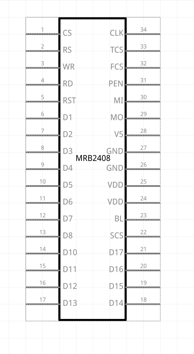
My part is already working, is this one: http://www.lcdwiki.com/2.4inch_16BIT_Module_ILI9341_SKU:MRB2408, it connects and everything is fine, i did it myself from zero using inkscape.
Now for my questions:
-
In the schematic view, do i need to put all the internals schematics of this breakboard or only with this is enough?
-
For the PCB, what should i do, do the same shape but change the pads to the golden color and keep outlines only?
-
I noticed that if you have connections already done but you modify something in the SVG and load it again, you need to redo the connections… Is there any way for Fritzing to match the labels of the connectors with the part in inkscape? I know i can do a plugin and i can automate it, not an issue i just wanted to know if there is a built in already.
Thanks in advance!
That should be enough. A better bet would be to use Randy’s Inkscape extension to make a schematic but this will do.
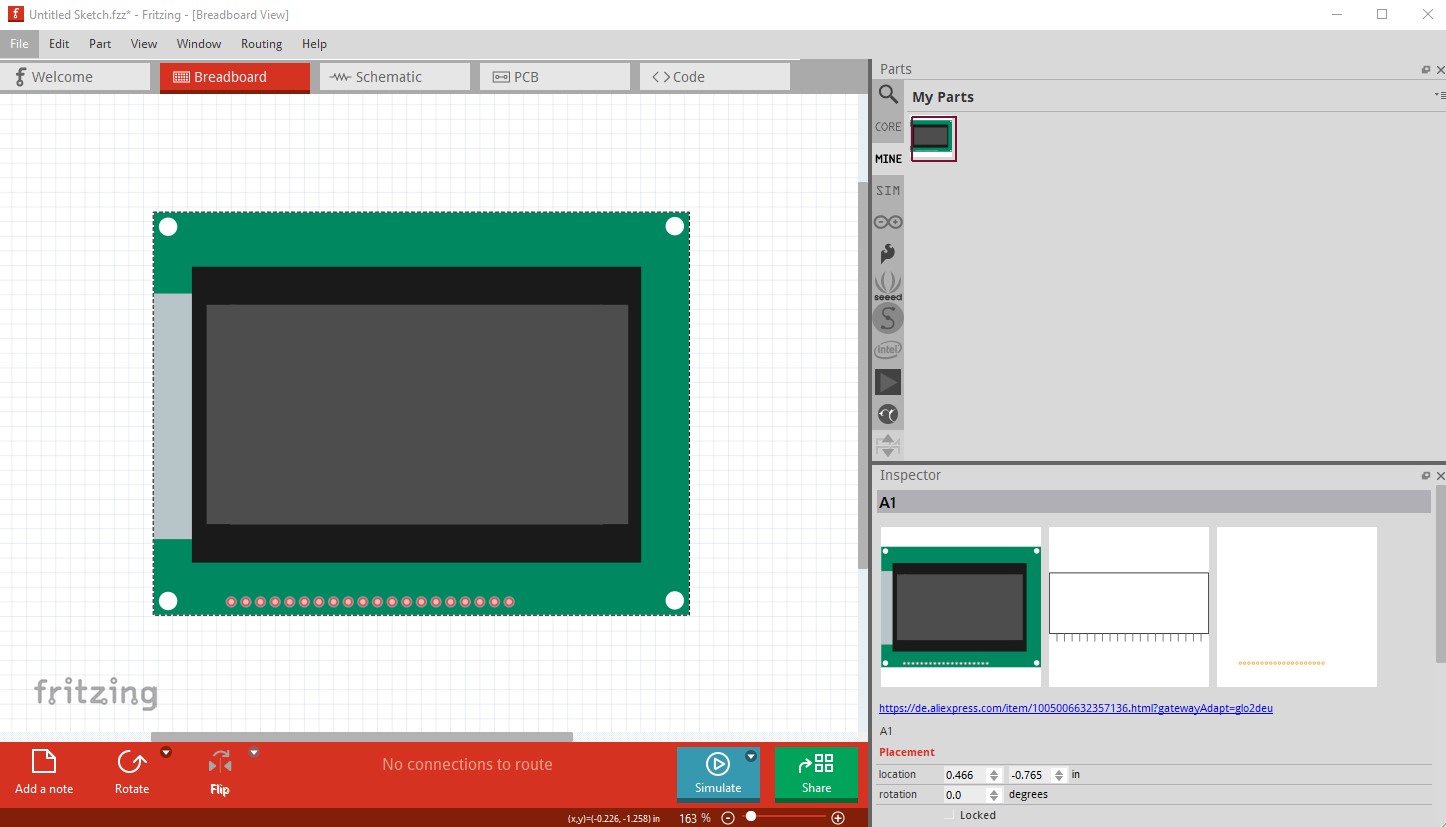
Pcb should look mostly the same as breadboard (and the real board!) with the pads in the correct place and an outline of the board as it would appear on a real board. Here is an example from the LCD I made for someone this morning
breadboard
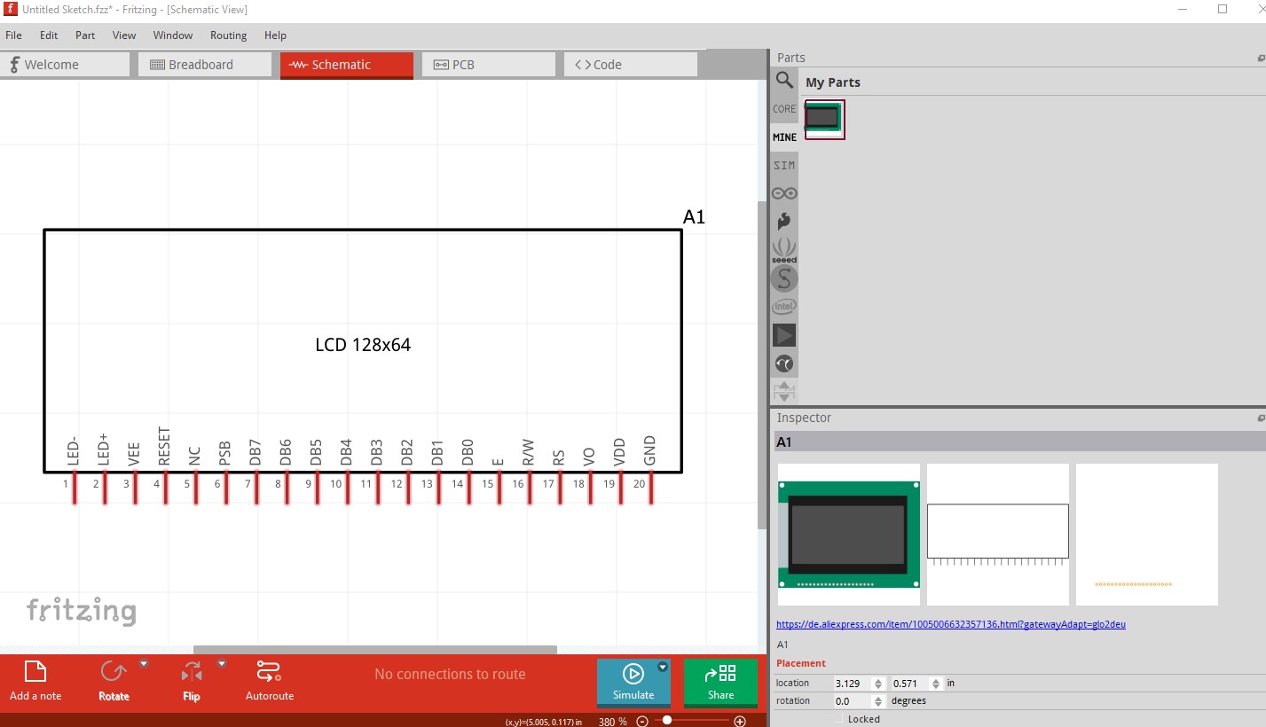
Schematic (generated by Randy’s Inkscape extension, it is pretty much the only thing I use for schematic any more.) There is an example in the tutorial I believe. It creates a schematic that meets the graphics standards where as your current one looks to be a generic IC schematic which has pins that are too long and incorrect colors.
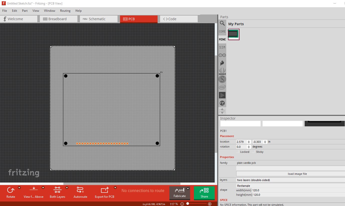
pcb is a copy of breadboard modified in Inkscape to turn the base in to a outline with no fill and a 10thou stroke-width and the pads converted from silver to the appropriate gold color (I don’t think that really matters though.) The holes are 0.038in (the correct size for a 0.1in header) whereas your are likely 0.03in (for an IC) and thus too small to fit a header. The mounting holes are not drilled by default. Because if you don’t want them you need to modify the part to remove them, where as if they are on silkscreen as here, you can drag a hole part in from core parts pcb, place it over the hole in silkscreen and adjust the hole size in Inspector to get the hole if you want it.
Hope this helps.
Peter
1 Like
Thank you so much Peter, that helps a lot, i will post it in the forum as soon as it’s ready!