No, the op amp pin outs are incorrect. From the data sheet for the tl082 here:
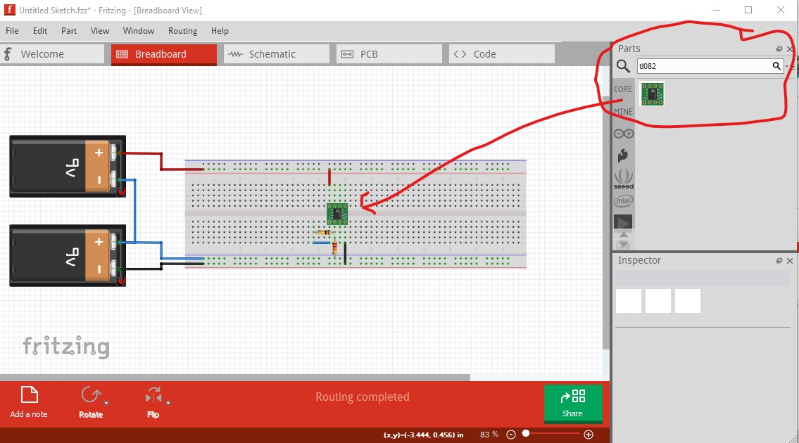
and/or the tl082 part (although it is smd) in core parts. type tl082 in to the parts search bar on the right (the magnifying glass) and it will come up, pin 4 is -V and pin 8 +V. Pin 1 is the first op amp output pin 2 is the -input and pin3 is the +input. In this image selecting the tl082 in core parts is circled in red on the right top.
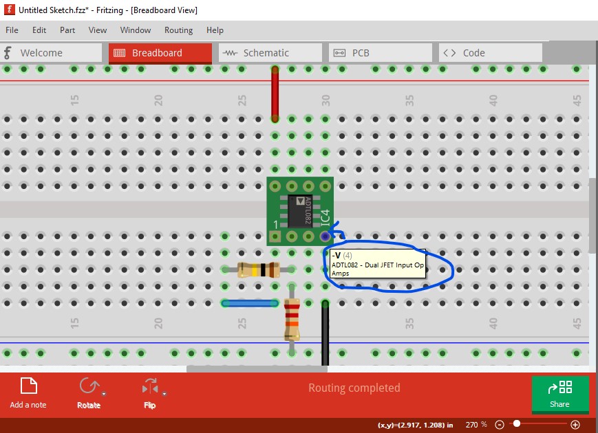
Here I hovered the mouse over pin 4 of the IC and it displays the function of the associated pin (-V in this case.) The bottom power rail is -V the one above it is ground and the top one is +V.
Peter