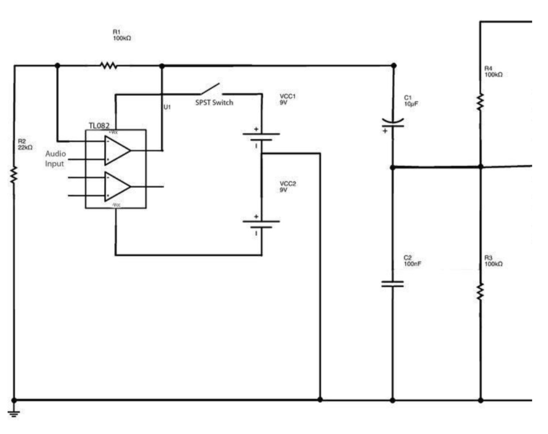
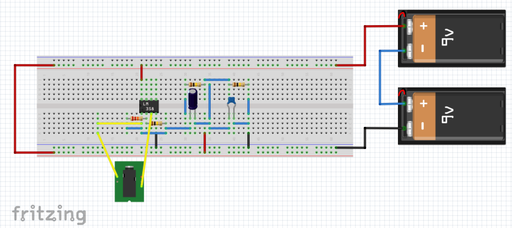
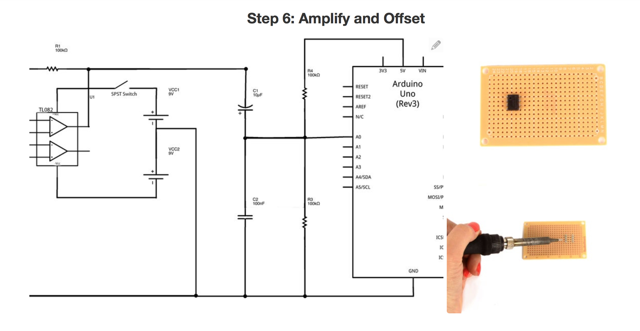
You probably first need to complete the schematic. There likely should be a dpst switch with the second pole on the bottom battery (as it stands the bottom battery is always connected which likely isn’t correct.) You need to assign pin numbers in the op amp in order to know what pins to connect to. R4 only has a connection on one end. Other than that, place the components on the breadboard and wire the components up according to the schematic (you could reproduce the schematic in Fritzing and it would give you rats nest lines for the connections in breadboard.)
Peter
Thanks for your response!
The R4 and R3 edges will be connected to the Arduino voltage.(R4 to 5V and R3 to GRD).I also connected the two resistors to my amplifier (TLO82).(The batteries in series is ok).But I’m stuck…
This is my progress.
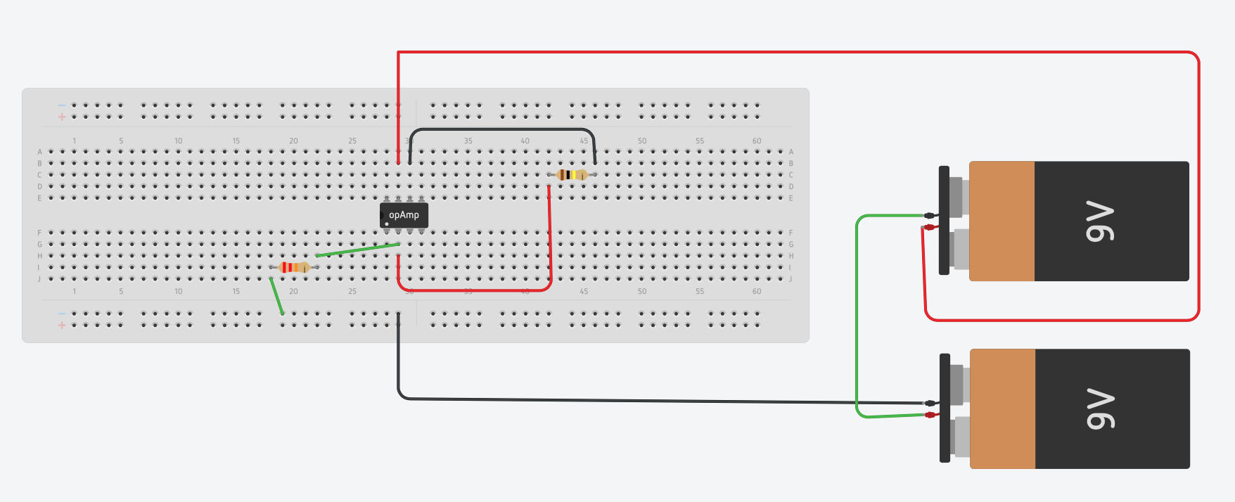
Am I in the right way?
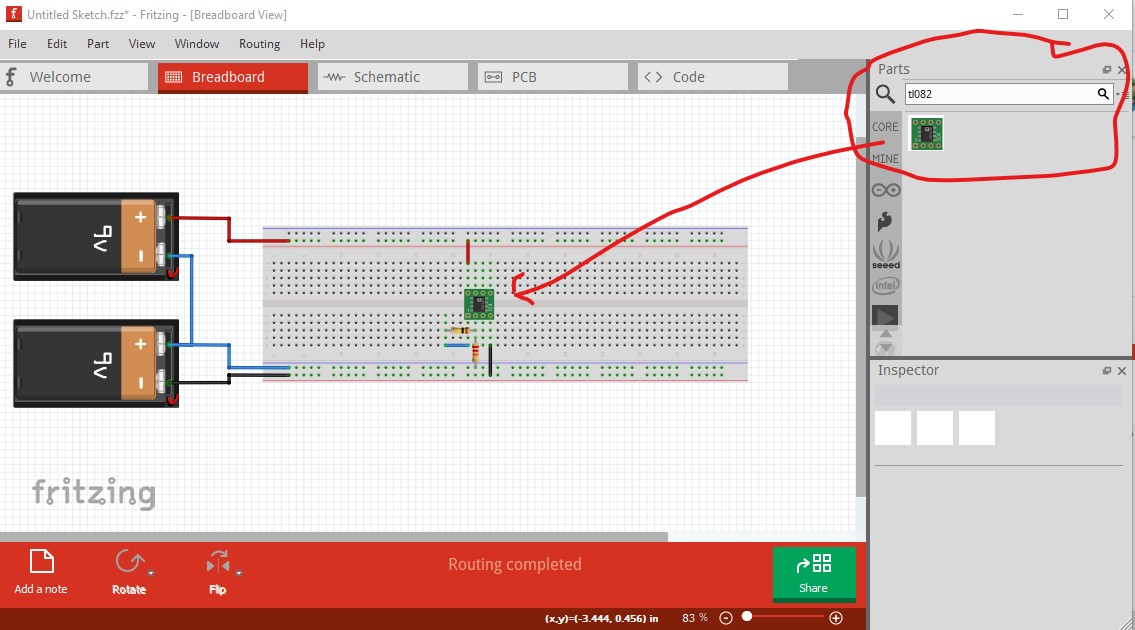
No, the op amp pin outs are incorrect. From the data sheet for the tl082 here:
and/or the tl082 part (although it is smd) in core parts. type tl082 in to the parts search bar on the right (the magnifying glass) and it will come up, pin 4 is -V and pin 8 +V. Pin 1 is the first op amp output pin 2 is the -input and pin3 is the +input. In this image selecting the tl082 in core parts is circled in red on the right top.
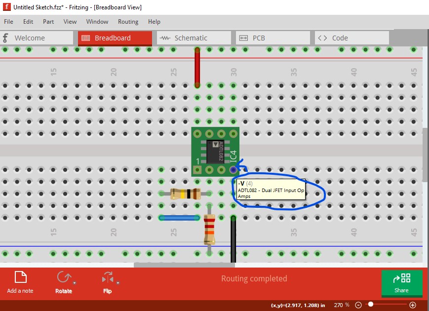
Here I hovered the mouse over pin 4 of the IC and it displays the function of the associated pin (-V in this case.) The bottom power rail is -V the one above it is ground and the top one is +V.
Peter
thanks again!
I’ll correct it and i will be back soon!
Well I couldn’t find on fritzing the TL082 so i used the LM358 (both have the same pins).
So i made a try on converting the full schematic on breadboard.
Here it is:
I hope this make sense
That will work fine, but the tl082 is in the latest parts release. You may need to check for updates (although Fritzing should automatically update the parts on every start.) You are missing a ground connection to the middle of the two batteries. The 22K resistor and the 100nf capacitor and R3 should all connect to ground and they don’t. You need to add a wire from them to the middle of the batteries as shown in my original sketch. As well the end of the input jack that currently goes to pin 1 (the output) of the op amp needs to go to ground instead. Also the black wire on the bottom closest to the batteries needs to be removed, that shouldn’t be going to -V but appears to be an output of some kind. If you post the complete sketch (the .fzz file) it makes it easier to see and correct problems.
Peter
Thanks a lot!
I’ll try to correct the spots you mentioned and i will post (the.fzz file) soon!
I made some improvements but i couldn’t correct them all.
Here is my progress:
fritz schematic to breadboard.fzz (9.7 KB)
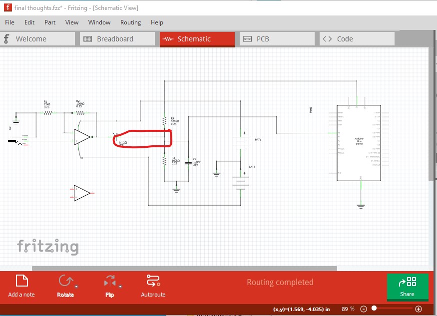
OK a fair few problems here. First you can’t (at least successfully!) connect a wire to a wire, you have to connect a wire from a connector on a part to a connector on a part.
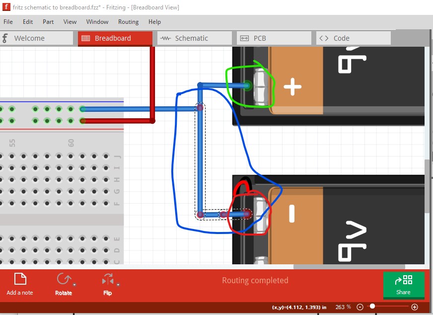
the wire circled in blue here is not connected. If you look at the connector on the battery circled in red you see the connection is red unlike the green (for connected) color of the connection circled in green on the other battery. Then the batteries are inverted (which I didn’t notice!) the negative terminal is going to v+ and the positive terminal is going to v- which would destroy the op amp.

Rotating both batteries 180 degrees (right click on the battery then select rotate->180 degrees) illustrates the problems: the unconnected wire is now obviously unconnected, ground is going to the wrong place and the polarities are wrong:

At this point I switched to schematic view and moved and rotated the various parts to match your original schematic. This shows a number of other problems as well. The rats nest lines (the dotted connections) show the connections made in breadboard.

R1 the 22k resistor has no connections (although it is connected in breadboard!), the top of r4 should have no connections but it connects to the output of the op amp. As noted the battery has no connection between the minus side of bat2 and the plus side of bat1 but does have a connection of + to + which it shouldn’t. So I corrected breadboard to both use the minimum number of wires and be correct which looks like this:
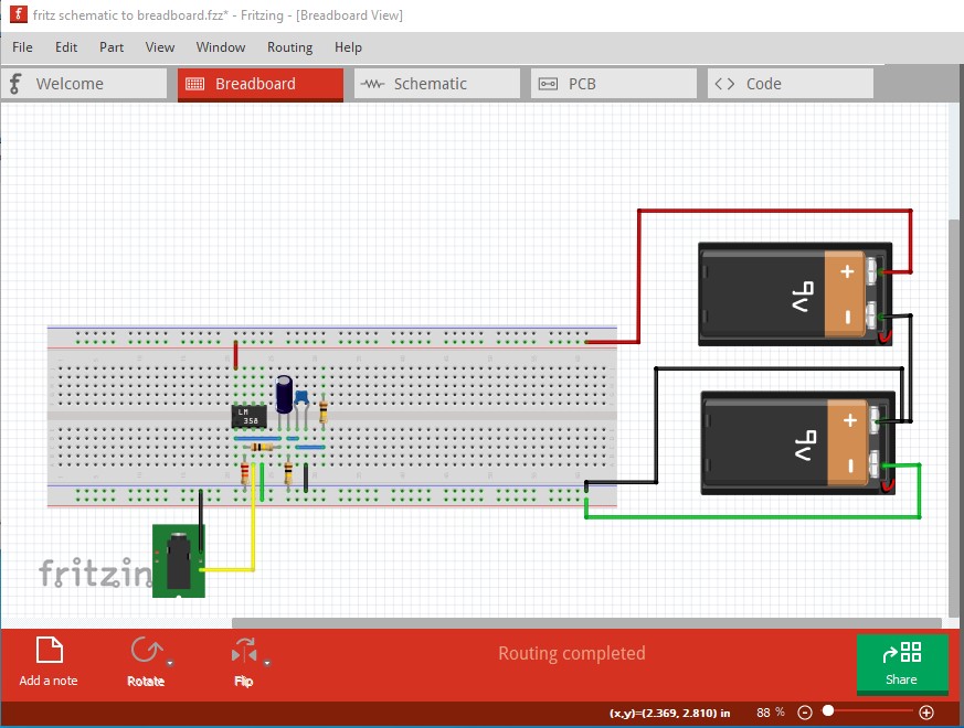
where the -v wires are green, ground is black and +v is red. This produces this schematic (with the rats nest lines routed properly):
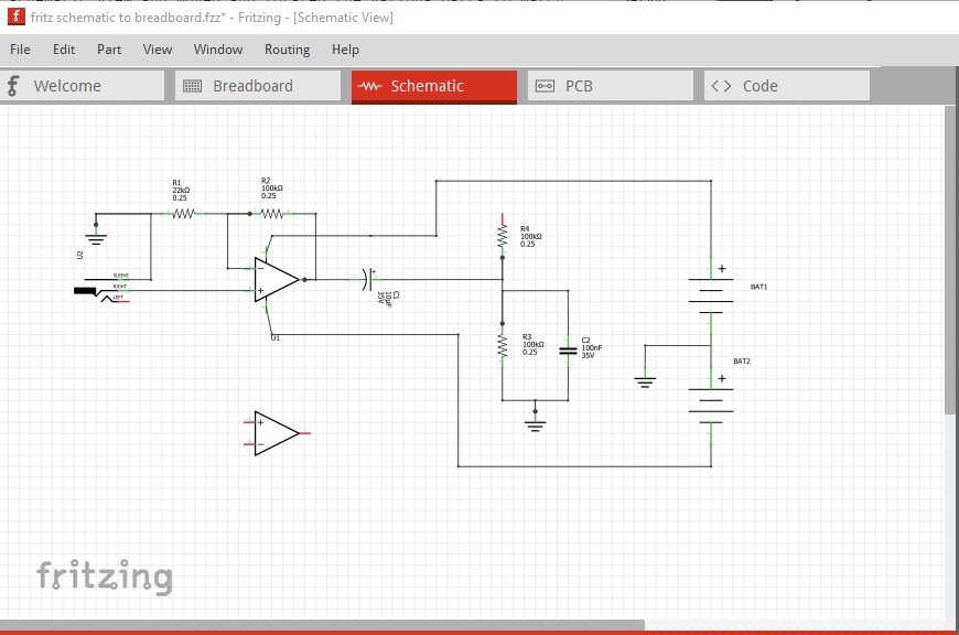
which matches your original schematic above. All of these changes are contained in this sketch:
fritz schematic to breadboard-fixed.fzz (12.4 KB)
Peter
Thank you very much!!
Now everything makes sense!
Especially with your explanation of the non connecting parts, using the fritzing schematic…You helped me develop a logic sequence on how to convert this schematic to breadboard and to future conversions that i may come across.
I have one more question.I can’t understand why we connected the red wire -V to the +V of the breadboard.
The important part isn’t the breadboard but rather the op amp. The op amp wants the positive voltage from the battery to the +v pin (pin 8) and the negative connection from the battery to -v (pin 4.) Originally they were connected backwards, the - pin of the battery to pin 8 and the positive end to pin 4 which would have put the power the wrong way across the op amp which would likely damage it. The op amp doesn’t directly get the ground wire from the battery, but it certainly cares about it. If the resistors such as r1 and r3 connect to -v (which I think was the case originally) the circuit won’t work because the input signal is referenced to ground. That won’t damage the op amp, but the circuit won’t work either.
Peter
Omg!
You opened my mind…!
I’m so thankful!
Hi again! i converted my schematic to breadboard with some last additions.
The final plan was to take a wire from the edge of R4 and join it to the Arduino 5V pin, a wire from R3 to the Arduino GRD pin, and finally a wire form the point they join R3,R4,C2 and join it to the Arduino Analog A0 pin.
I made those changes and finally i burned the op amp but i can’t figure out what is wrong.
Here is how it looks my final breadboard conversion.
final thoughts.fzz (14.8 KB)
Here is also the final schematic i tried to convert.
My best guess is that you have a wire wrong in the physical breadboard. The Fritzing sketch looks fine. Here I completed routing in schematic and it matches the schematic above.
The only potential issue I see is that a large enough input signal could over drive the analog input to the Arduino to more than 5V. That might damage the the Arduino. The op amp has a gain of about 5, so an input signal of about 1v peak to peak would be the limit on the input. With no input, the Arduino A0 pin should show half scale (about 2.5V) so disconnecting the wire circled in red here and checking that the A0 input to the Arduino reads mid scale would be a good start. The 2 100k resistors should be giving 2.5V dc to the A0 input of the Arduino. The output of the op amp (when connected) should drive that towards towards 0V and then towards 5V depending on the input signal. If you have a voltmeter available, measure the voltage between ground and pin 8 of the op amp which should be +9V, and then between ground and pin 4 of the op amp which should be -9V. To blow the op amp, I expect one of those is backwards. Once that works, short the op amp + input (the signal input) to ground and measure the output voltage on the output of the op amp (pin 1). The output should be 0V if all is working correctly. Once that works, add a diode (either a 1n4148 small signal diode or a 1n4001 diode will do) and a 22k resistor between the Arduino 5V pin and ground. That will give you .7V at the cathode of the diode. If you connect that to the op amp input you should get around +3.5V at the op amp output (.7 v * gain of 5.) The capacitor will block the DC from getting to the the Arduino, so you need to measure the output at pin 1 of the op amp. That tells you that the op amp is working and supplying an input signal should then make the circuit work. Here is a sketch with the diode and resistor to create an input voltage added:
diode-added.fzz (18.0 KB)
and a screen shot of schematic
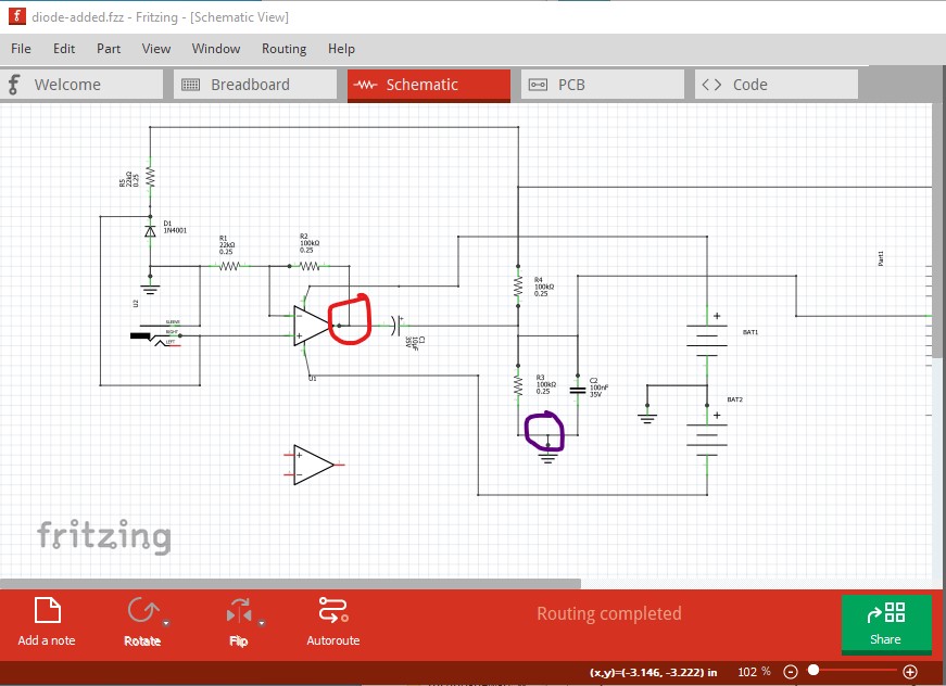
the red wire from the voltmeter on pin 1 of the op amp (red circle) and the black wire on ground (black circle) should read 3.5V if all is well.
Peter
I have no words!Thank you very much!!!