My best guess is that you have a wire wrong in the physical breadboard. The Fritzing sketch looks fine. Here I completed routing in schematic and it matches the schematic above.
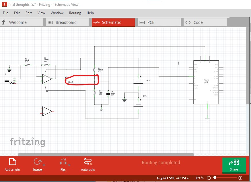
The only potential issue I see is that a large enough input signal could over drive the analog input to the Arduino to more than 5V. That might damage the the Arduino. The op amp has a gain of about 5, so an input signal of about 1v peak to peak would be the limit on the input. With no input, the Arduino A0 pin should show half scale (about 2.5V) so disconnecting the wire circled in red here and checking that the A0 input to the Arduino reads mid scale would be a good start. The 2 100k resistors should be giving 2.5V dc to the A0 input of the Arduino. The output of the op amp (when connected) should drive that towards towards 0V and then towards 5V depending on the input signal. If you have a voltmeter available, measure the voltage between ground and pin 8 of the op amp which should be +9V, and then between ground and pin 4 of the op amp which should be -9V. To blow the op amp, I expect one of those is backwards. Once that works, short the op amp + input (the signal input) to ground and measure the output voltage on the output of the op amp (pin 1). The output should be 0V if all is working correctly. Once that works, add a diode (either a 1n4148 small signal diode or a 1n4001 diode will do) and a 22k resistor between the Arduino 5V pin and ground. That will give you .7V at the cathode of the diode. If you connect that to the op amp input you should get around +3.5V at the op amp output (.7 v * gain of 5.) The capacitor will block the DC from getting to the the Arduino, so you need to measure the output at pin 1 of the op amp. That tells you that the op amp is working and supplying an input signal should then make the circuit work. Here is a sketch with the diode and resistor to create an input voltage added:
diode-added.fzz (18.0 KB)
and a screen shot of schematic
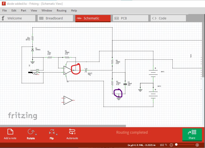
the red wire from the voltmeter on pin 1 of the op amp (red circle) and the black wire on ground (black circle) should read 3.5V if all is well.
Peter