Hi,
I am trying to make a part from scratch and have a few problems
The first one is in the breadboard view.
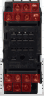
The picture I get after assigning the pads with inkscape is
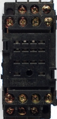
What I want is
I have hidden the pads in inkscape but they still show in fritzing, is it possible to hide them? omron for the forum.fzz (363.4 KB)
The second problem is I am trying to use fonts whilst making the schematic of the relay base and fritzing only supports OCRA and droid fonts, it substitutes anything I use including OCRA Extended, which is the only one inkscape uses and changes the size of the font dramatically. Is there any way around this?
If you only have a few problems you are doing very well already (as is indicated by your breadboard example here).
[quote=“matelot, post:1, topic:7443”]
The first one is in the breadboard view.
The picture I get after assigning the pads with inkscape is
image
What I want is
image
I have hidden the pads in inkscape but they still show in fritzing, is it possible to hide them?[/quote]
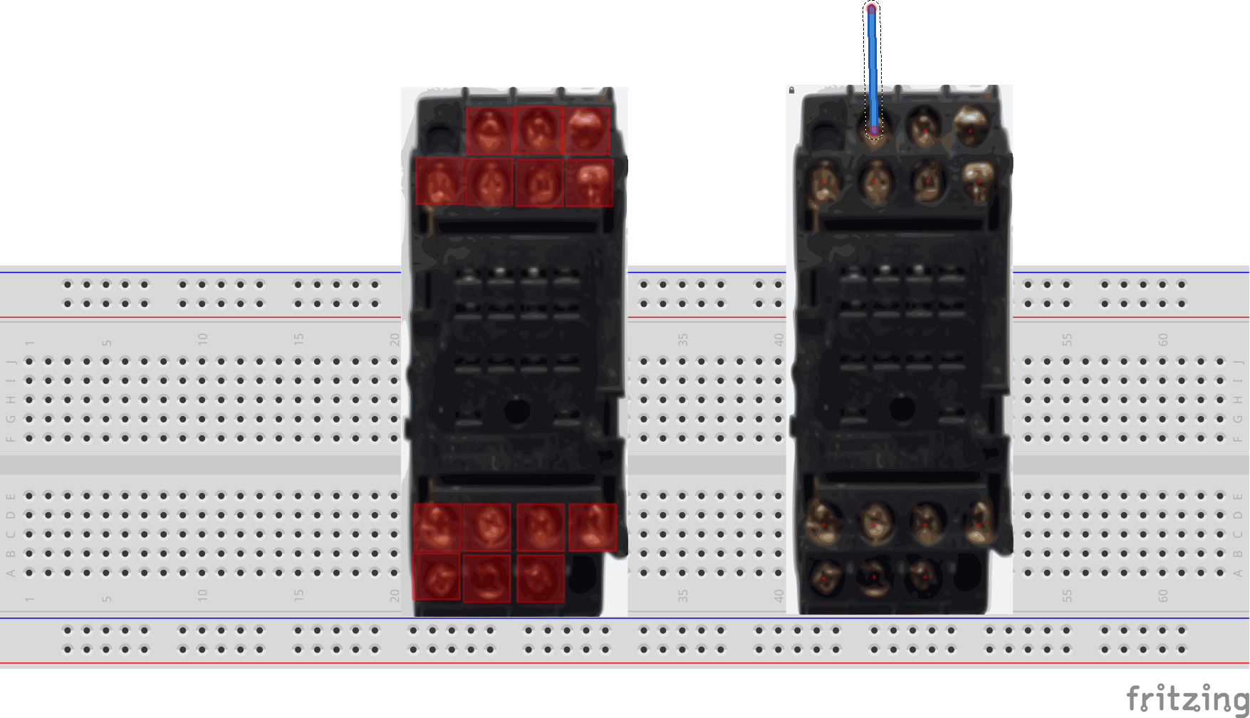
Unfortunately no, the best you can do is make the red dot smaller. What is happening is Fritzing is coloring the connector pin red to indicate no selection, when you connect a wire it will turn green. In this part (which has a new moduleId so you can load it along side your current one) I did the following in Inkscape:
ungroup the entire drawing move connectors in sequence to the bottom via xml editor set style to fill:none;stroke:none;stroke-width:0 for all connectors reduce height and width from .222in to .01in for all connectors and move them back to the center of the pin. Align all pins so y is the same across the line and X is the same as all the pins above it so the pins are in a square matrix so the wires connect neatly (preferably on .1in boundaries but these look to be .056in or the like terminals). edit->select all, Resize the page, group and name the group breadboard (to set the layerId so the part will export as svg) then save as plain svg.
If you install the fonts in the download Inkscape will find and use them. If you want to use alternate fonts for some reason (although I dislike it, as it makes changing parts much harder!), you can change the font in to a path as well. In addition I ran your part through the part checking script and there are a number of other errors in it, but I just addressed this particular problem here.
edit:
If you are making parts, it is a good bet to download and use the 0.9.4 pre release version from github. I fixed a couple of bugs where badly formatted parts will hang Fritzing that are in that build. Instructions on finding it are here: