I am trying to alter a part from the library with my very limited knowledge of how to do it.
I managed to load the original relay from the fritzing library into inkscape and altered it to this (the original has only got one pole, I want 4).

I have loaded it back into what I think is the directory for “mine” parts before I finished it just to see if it showed up, closed and reopened fritzing but it is not there. I am obviously missing a step and most of the other ‘svg’ files in the directory have a large amount of numbers and letters within their names which mine doesn’t, is this something to do with fritzing seeing the file?
There is also another picture behind the one you can see above that looks like solder pads but I don’t need them as I am just going to use it in the breadboard section for now.
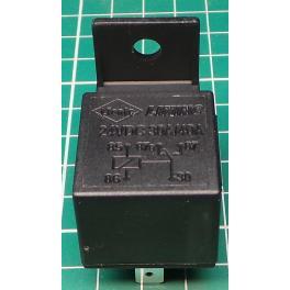
My original is a car relay in the parts directory, I can’t find it but if you search ‘car relay’ it shows up.
Can anyone tell me what I am doing wrong please.
Start here
OK thanks I will take a look at that.
Might want to look at this as well:
Following the video and the other info you gave I have succeeded in altering the ‘car relay’ into a four pole two way relay. The part I found most difficult was changing the ID of the file but using notepad and altering the line moduleId=“4wayrelay_35157ff6d6f48da00b0a28d5dbaca431_7”> to a new last number (7 by now) I managed to get it to go in. I have only altered the breadboard view but I am sure I could do it with the other views if I needed it. Now to write it all down so I don’t forget it. 
If you save something as a new part, and import the different svgs into the Editor, all those files get assigned automatically.
What just altering the breadboard part doesn’t do is alter the connection points. When I try to connect wires to the part in breadboard it just links the wires to the old pads. I suppose I will have to try to change all the pads in the PCB view. I believed I had it. OH well start again.
I don’t see how to import the different svgs into the editor, there is no command for that?
I just tried to use the original ‘car relay’ in the parts library and that doesn’t link wires to the pins either. It looks as if it tries to link them to the pins of the relay and not the pins of the drawing, do you agree with that?
You have to mod all the svg views and assign pins in FZ Editor, like in the video.
the breadboard view doesn’t see them as pins. Take a look at the car relay and try to link wires to it. You can see the position of the the connections on the relay as ‘foggy’ squares ‘under’ the breadboard view, it tries to link the wires to these.
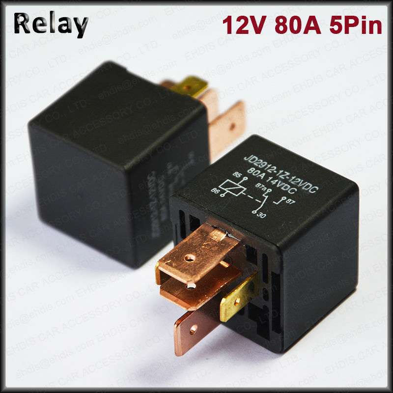
That is just a silkscreen SCH of the circuit, so those ends are not connectors. The connectors are those 5 brown rectangles, that are the spades that plug into a socket.
If you post your part here we could probably make better suggestions for changes. A quick look at car relay in core indicates to me it is pretty broken though.
It looks like what it is supposed to be, what’s broken besides the pins could look a bit better.
While I guess broken is too strong, will ugly do  ?
?
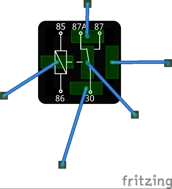
while technically the connections work, the presentation however is ugly. I think the terminals at least in bb should be oriented on the circular terminals on the drawing as one would expect rather than on the physical terminals as is happening but that may just be me … As well schematic doesn’t align to the grid.
I like ugly… and I won’t even ask what you are trying to do…
Even though you didn’t ask  : connect wires to the relay. As you see the result isn’t exactly intuitive for the newby. I’m of the thought that having the breadboard wires connect to the silkscreen connection circles on the part would be a lot better than to the real physical terminals as at present. Coming at this cold (without having drawn it ) I’d have a hard time figuring out what the connections actually do.
In real life you can’t plug that into a BB - it has a socket -, it has to be with wires. The only thing is that the pins look a bit thick and hard to see.
I know about as much now as i did before I didn’t ask… 
Isn’t that the whole point of BB view, real life, so that it can be made by beginners in real life.
The SCH is in SCH view so no need to duplicate it again in BB view.
I guess you can argue it either way. I’d prefer to see the pins come out where the numbers are (one coil connection at 86 with the terminal at the dot another (the wire currently connected in the middle of the part) on 85. The wire beside 87A actually on the silk for 87A and the wire to the right side connected to 87. Which follows the function of the part which (to my mind at least0 the current connections don’t even though they are probably physically accurate. This whole discussion started because the original poster is trying to modify this part to have more contacts and is having problems of some kind (what kind I’m not entirely sure of because there hasn’t yet been a part posted as far as I know).