I’m creating a molex 2x02 and molex 2x03. But i don’t understand how to resolve a error im PCB create.
If you upload the .fzpz file for the part I will have a look at it. Upload is 7th icon from the left in the reply menu.
Peter
SOLVED
I used molex 5x02 to start.
Export to SVG and edit.
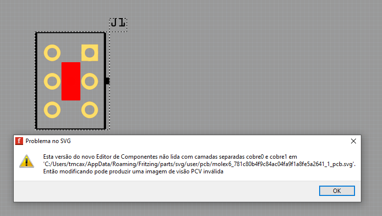
But Layers dont are exported correct.
After made layers like videos, work.
molex 6pin minfit jr.fzpz (10.5 KB) (upload://tCtxwSXKeRL7DwksDwwYhHmLumU.fzpz) (8.3 KB)
molex 4pin minfit jr.fzpz (8.3 KB)
This part is mostly fine, it however lacks terminalIds in schematic which causes this:
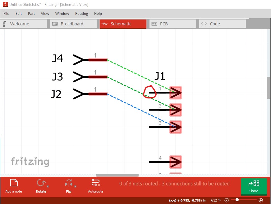
it is desirable that the wires connect to the end of the pin (circled in red in this image.) To do this you need to make some changes to the schematic svg.
Currently it looks like this:
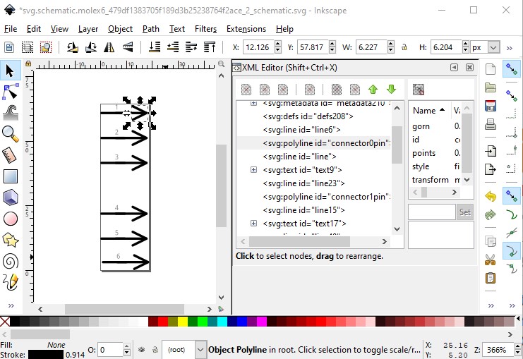
where the connector is the arrow at the end of the pin. That needs to change to this:
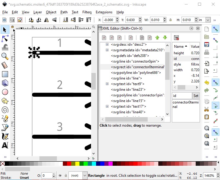
where the connector0pin label has changed from the poly line to the line just above it and a new 10 thou by 10 thou rectangle positioned on the end of the pin and labeled connector0terminal has been added. This will convert your part to look like the header connector in the first image. The line that ends in the rectangle will be red as the pin and the wire will terminate on the rectangle at the left end (as the wire from the header connector to your part does.) Another thing to verify is the hole size in pcb. At present (from the gerber drill.txt file) the holes for the pins will be 0.055800in. You need to verify in the connector data sheet that is sufficient size to fit the pin and if not adjust the size in the pcb svg file (I can tell you how if needed.)
Peter