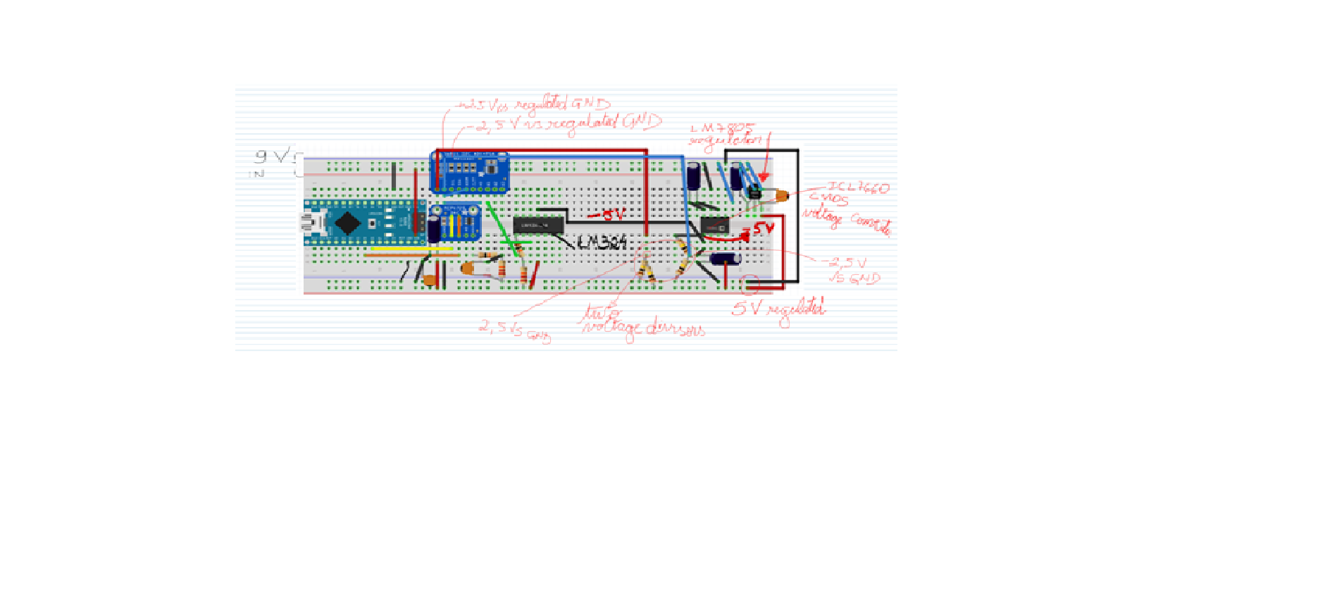
I am working on a low cost potentiostat-galvanostat assembly project. In the first step I am working on the triangular ramp (triangular wave). I am using the Adafruit MCP4725 DAC in bipolar mode (page 31 of the datasheet). From the photo, you can see that it is working perfectly, generating a ramp of approximately -2.5 to +2.5 V vs GND, I thought it was great. Now I decided to include an ADS1115 ADC to measure the potential generated by the MCP4725. From the ADS1115 datasheet I know that the power must be between 2 and 5.5 V and I also know that I can measure potentials between -0.3 V vs GND and +0, 3 vs VDD. As the signal generated by MCP 4725 goes from -2.5 to +2.5 V vs GND, if I try to measure this signal I will burn ADS1115. For this reason I used the ICL7660 converter to generate -5.0 V vs GND. Then I used two voltage dividers to get -2.5 vs GND and + 2.5 vs GND to use in the ADS1115 supply, so -2.5 goes to GND and +2.5 goes to VDD. The problem is that it is not working, when I run the program to scan I2C addresses the arduino does not recognize the ADS1115 powered in this way. I must say that in reality my voltage divisors result in -2.33 and 2.37 V vs GND but it still theoretically works to feed ADS1115. I don’t know if the voltage level changes anything at the output of the SCL and SDA pins, I don’t know if it would be the case of using an MEGA arduino because it has two I2C outputs because I’m using a nano arduino. Thank you for your help.
You have a level translation problem. There are several potential solutions:
-
Use an op amp to raise the level of the analog signal from ±2.5V to 0 to 5V. Disadvantage is you likely lose precision in the translation.
-
level translate the digital signals in to the ADS1115. To do that the easiest way is likely optoisolators like this:
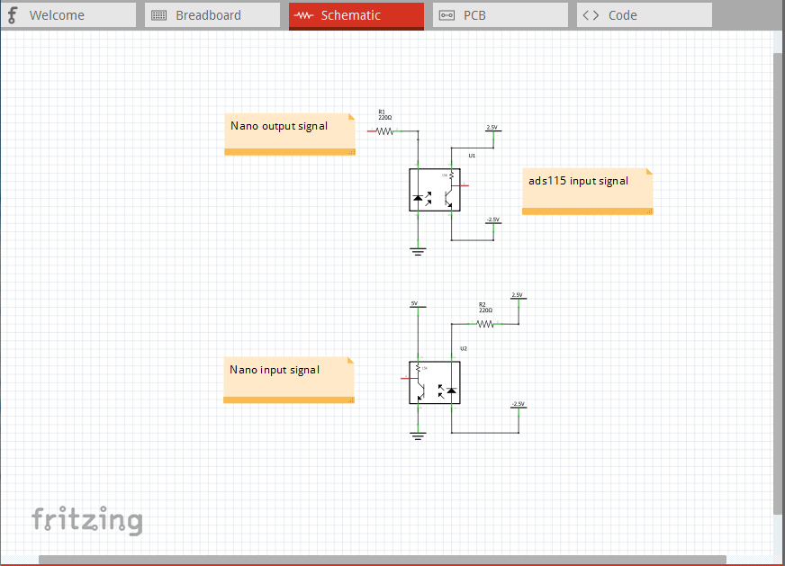
This is probably what I would do, as it avoids the analog problems. I’d use totem pole output opto isolators, although you may not need the speed (the versions shown will have a long rise time as it isn’t actively driven high.) You will likely also need adjustable voltage regulators for the +/- 2.5V supplies rather than the resistive dividers (that is likely a good idea anyway) because the optos will want about 20ma of drive current each for the diodes. The likely reason that the nano doesn’t see the ADS1115 is that a digital low is 0.7V from the nano, but that translates to +2.5V (because of the -2.5 ground reference on the ADS1115) which is likely above the threshold for a low level at the ADS1115. The 2.5V output from the ADS1115 is just barely above the high level to the nano which is likely about 2.4V (but may be higher) thus the level translators.
Peter
Thanks for your help although I didn’t understand it very well due to my very limited knowledge in electronics. From what I understand the fundamental problem with my system is that the GND must be common and the GND of ADS1115 is -2.5 vs GND of the arduino. My knowledge of optoisolators is basically zero and my box of electronic tools is quite limited, that is, I have a few op-amps and basic components.
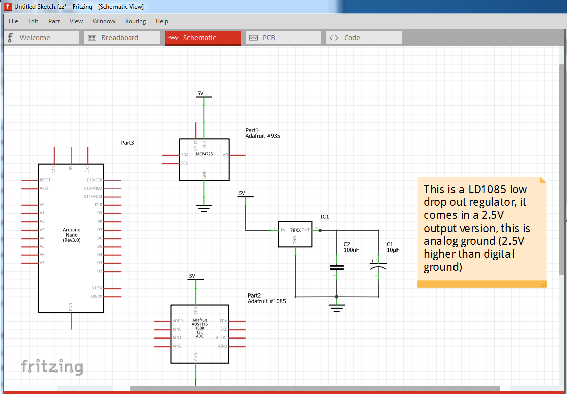
Essentially yes. A low digital level is typically from 0V to 0.7V (higher than .7V not considered low). So a low from the Nano is at +2.5V (but 0 to the Nano) compared to ground on the ADS1115 and thus not seen as a low to the ADS1115 so the I2C input on the ADS1115 sees nothing but a high level and never activates. The same should be true on the MCP4725 so I don’t understand why it works. As well I just realized this is I2C, and the optos won’t work (I was thinking of spi where they will.) So I think the alternative is this: replace the +/- 2.5V supply with a LD1085 2.5V LDO linear regulator. That becomes analog ground (and thus both the D/A output and A/D input are from +2.5V to -2.5V relative to analog ground but appear to be 0 to 5V to both chips and the nano on digital ground, so you may have to do some scaling in software to convert the unipolar 0 to 5V representation in to twos complement to get back to -2.5V to +2.5V.) It simplifies your circuit by a bit and eliminates the need for level shifting the I2C (which is likely to be difficult.)
Peter
Thanks for your help. I’ll see if I can find LD1085 in my city. If not the waiting time is one month. I have the LM317T in my stock, it might work. The MCP4725 worked because it shares the GND with the arduino. I will study your answer because as I told you, my knowledge of electronics is very scarce.
I would like to share with you a crazy thought: as we know the problem is that ADS1115 does not share the ground with the Arduino. Here goes my thought: if I power the arduino by placing it in its GND -2.5 and in the VDD +5.0 (using my LM7805, the ICL 7660 and my voltage divider). That way I wouldn’t need to use the MCP4705’s bipolar mode and could thus measure negative voltages with the ADS1115. If that works, you would probably have to disable the USB cable’s VDD and GND. Please tell me what you think of this craziness.
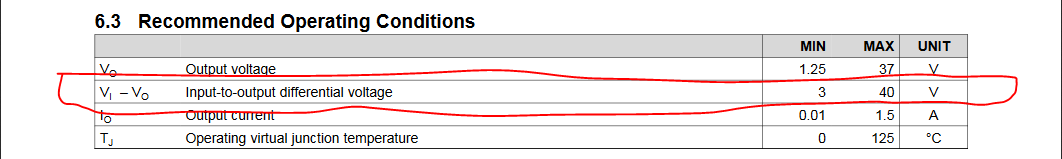
It will work fine, but it needs an input voltage source greater than 5V. The photo in the initial post is blurry, but it looks like there is a +9V source present (maybe ![]() , it would be helpful if you posted the .fzz file for your sketch! Upload is the 7th icon from the left in the reply menu (you probably used it for the photo) and will accept .fzz files. The 317 won’t work (as the LD1085 will) because its input to output differential is 3V minimum and you only have 2.5V from a 5V supply (thus the LDO for low drop out) L1085 which requires something like 1.5V input differential. From the LM317 data sheet:
, it would be helpful if you posted the .fzz file for your sketch! Upload is the 7th icon from the left in the reply menu (you probably used it for the photo) and will accept .fzz files. The 317 won’t work (as the LD1085 will) because its input to output differential is 3V minimum and you only have 2.5V from a 5V supply (thus the LDO for low drop out) L1085 which requires something like 1.5V input differential. From the LM317 data sheet:
That would at least let you experiment until the L1085 arrives.
Two problems with this: first (and most serious) the Nano’s maximum supply voltage is 5V, with this circuit you will be giving it 7.5V (2.5V + 5V) which will likely damage the Nano. The second problem is that the ICL 7660 can only supply less than 100ma (I think it is even less than that) and the Nano draws a fair bit more than that so the -2.5 volt power supply would likely collapse. I’d missed that the MCP4705 had a bipolar mode, so you can do the same thing by running the MCP4705 in unipolor mode from 5V and using analog ground from the 2.5V regulator and everything should be happy. Your circuit will see an input voltage of -2.5V to +2.5V referenced to the 2.5V regulator output, and the D/A and A/D see 0 to 5V as their input and output and everybody is happy.
Peter
Hello, thank you for your help. I upload the file. Please note that you don’t see ILS7660, you see TMP01 because I don’t have the ICL7660 library. Please disconsider TMP01 - That is the reason I poste a picture on my first post.
It is possible to achieve 2,5 V on LM317, I did it using the informations on this site: https://www.eleccircuit.com/lm317-voltage-regulators/
I did some suicide tests with my arduino nano. Example, with an LM7805 and ICL 7660 I got +5 and -5V. I put -5 V in the GND of the arduino and + 5V in the VIN and it incredibly worked, that is, in addition to running the software, it communicated with the computer and the 5V output of the arduino was used to power the MCP4725 (here I used unipolar mode) and ADS1115. In this case, the triangular ramp generated on the MCP4725 (unipolar mode) was between -4 V and -1 V vs GND (say, GND from my 9V source that I fed the LM7805). This seems to show that the hypothesis of your last paragraph did not materialize.
I played around with the LM317 and ICL7660. I actually got 2.5 V (and -2.5 V with the ICL 7660) but it didn’t work to power the Arduino.
With +3.5 and -3.5 V it was possible to power the arduino. The triangular scan generated in the MCP4725 unipolar mode was between -2.30 and +2.42 vs GND of the 9V source when the computer was turned on so that I could see the ADS1115 output between 0 and ~ 4.8 on the serial monitor, vs Arduino GND.
Interestingly, when I disconnect the computer, the voltage range generated by the MCP4725 is between -1.2 and 2.4 vs GND from the 9V source. I think the connection with the computer’s USB cable helps to power the arduino and so I get better results.
I think this last experiment is close to what I need but I would like to learn what you gave me to use the LD1085 (since I can get 2.5 V on the LM317) but I didn’t understand the design, my knowledge in electronics is so scarce like my electrical components. Is it possible to explain better your scheme?
Thank you so much.
Potenciostato-Arduino.fzz (47.7 KB)
It is currently late here, my network connection willing, I’ll answer this one tomorrow. The quick answer is that while the chips will run with the supply voltage too high it stresses the chips and they will fail sooner (possibly much much sooner.)
edit:
OK let us see if I can explain what I mean more clearly. Assume the D/A and A/D are connected to digital ground, and VCC is +5V. The regulator is in place powered either from the 5V source or the 9V source and is providing +2.5V relative to digital ground. Now lets step through a sweep of the voltage to create your triangle wave looking at the voltage relative to digital ground, and analog ground (which is the 2.5V regulator output.)
  	Digital ground voltage    analog ground voltage

		0V                    	-2.5V   (0V - 2.5V)
		1V                      -1.5V   (1V - 2.5V)
		2V                      -.5V    (2V - 2.5V)
		3V                      +.5V    (3V - 2.5V)
		4V                      +1.5V   (4V - 2.5V)
		5V                      +2.5V   (5V -2.5V)
The Nano and the D/A and A/D are running at 5V within spec, the circuit you are driving sees a signal varying from -2.5V to +2.5V as desired because the output voltage is being subtracted from the 2.5V ground offset value. So when your software sweeps from what it thinks of as 0 to 5V the output sees a sweep from -2.5V to +2.5V as desired.
Peter