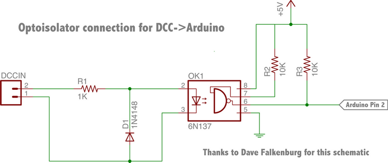
The circuit is supplied by a 15v ac dcc voltage which has both a power and digital command component. My circuit is effective a 5v dc supply in parallel with an optocoupler circuit; the circuit I used is shown in the link above.
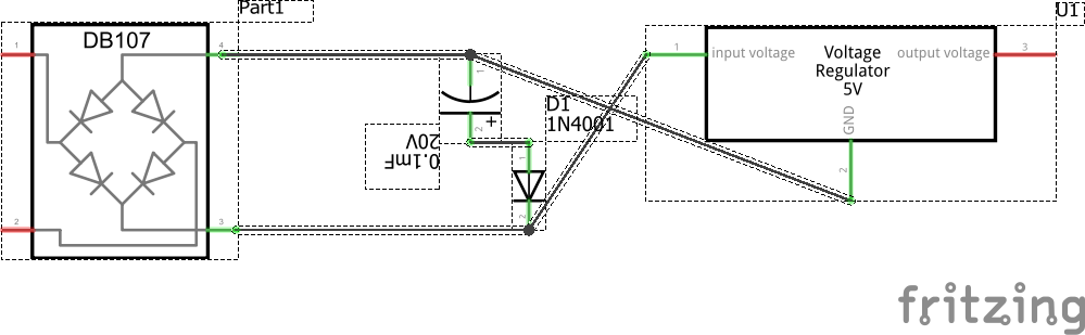
My circuit consists of ac in at J2 J4 Bridge rectifier to a 5v volatge regulator at IC2 for a 5v supply for the lighting and the digispark. In parallel with the optocoupler circuit. The optocoupler circuit requires 5v derived from the 5v dc supply. The optocoupler circuit sends a logic signal to Pin 2 of the digispark and the lighting is controlled via pins 1,3,4 and 5. I have shown tracks to holes in the board so that on the other side of the board I can solder sections of 5v LED self adhesive strip which can be independently controlled at J6,J7,J8,J9 with J10, J11,J12,J13 as ground.
I have also left holes at J1 and J5 in order to add a capacitor to provide a"stay alive" function for the dc supply. Since the capacitor is massive compared to the other parts I intend to solder flying leads to J1 and J5 and hide the cap somewhere in the body of the coach. As it is the components fit into the roof curve without too much difficulty.
Using the input from Micro Merlin (Thanks for the input) I revised the board and had some samples made, fully expecting to have to correct my mistakes. Mistakes were: Bridge rectifier around the wrong way,missed out a resistor, missed out a track from the optocoupler to the Attiny85. Despite this, once I rectified these errors on the sample boards it works!!! Lights go on and off from a dcc controller and when placed in a coach and pick up from the track lights go on and off. Job done I thought. I have modified the board to rectify my errors and the latest version is below. I have spaced things out to allow for components to be bent over to allow for a very small headroom. I also discovered that the ATTiny 85 Micro USB has a different footprint to the ATTiny 85 USB, the row of pins is 0.1" closer on the Micro USB so to allow for using both I added an extra header
There is now a problem which I cannot fathom! Everything works right up until the time I add a capcitor at C1. Then no response from the dcc circuit lights do not turn on or off. remove the capacitor from the circuit and everything works fine.
So far I have tried:
separating the input feed----same outcome
removing the track between the voltage rectifier and R3 connecting it directly to the digispark— same outcome
removing the link between C1 and the Opto connecting the opto to GND on the digspark— same outcome
a combination of all of the above----same outcome
Sa5v supply to digispark3H.fzz (43.9 KB) me thing happens all works fine until Capacitor added at C1 then no response form the dcc,
assisting it with 2.5lb lump hammer–different outcome same result!
Does anyone have any insight into what is happening. I cannot see what difference the Capacitor would have. It is there to provide a stay alive function for the regulator otherwise the lights will flicker. I do not see how it can be interfering with the dcc signal but clearly it is. Can anyone suggest a work around. Even better does anyone understand what is going on!?
Thanks for any suggestions 5v supply to digispark3H.fzz (43.9 KB)
I don’t have a clue, but maybe look at the datasheet for the 6N137 for a recommended circuit and copy that to your design. Also there is no value for C1, in fact you used a 2 pin header.
While I am on a borrowed machine and don’t have Fritizing to look at the sketch, a capacitor will short an AC signal (which I assume the dcc is. If your intent is to charge a capacitor to maintain the supply voltage, a diode in series with the capacitor may help. The diode will block the the capacitor from shorting the dcc signal but allow the capacitor to charge and maintain the power. This would look like this
power and dcc conneciton – diode – capacitor – power supply.
edit:
I took a copy away and had a look. It looks like your circuit is wrong. Assuming the bridge rectifier part is correct in schematic, it is mis-wired. I am assuming DC around 12V comes in from the tracks on j1. The optocoupler pulls off the dcc signal and level translates it to 5V and feeds that to the digspark (that part looks correct.) The bridge rectifier needs the DC going to the two ac input pins on the left and the ground and positive outputs going to the capacitor on the right. In this case the bridge rectifier has been moved to take input from the tracks, and feed both the optoisolator (removing the requirement for the diode on the optocoupler) and the capacitor (the diode in front of the capacitor stops the capacitor from shorting the dcc signal to the optocoupler, the diode needs to have the same amp rating as the bridge rectifier, not the current signal diode!) The advantage to this is that it will allow dcc to work no matter which polarity the tracks are (assuming there is an hbridge motor driver providing speed and direction control to the train motor.) In the original case, if the track polarity is not positive on pin 2 of J1 (with negative on pin 1) the dcc signal will be blocked by reverse diode in the optocoupler and dcc will not work. With the bridge rectifier between the tracks and the optocoupler, dcc should work with both polarities of the tracks (tne bridge rectifier will route the positive and negative to the correct places.) As well if you wish you could connect Vin on the digispark to the + terminal of the capacitor and remove the connection to the connector (which I assume provides 5V from somewhere else) as the digispark appears to have an internal voltage regulator although that isn’t done here.
is the corrected circuit with all the pcb traces deleted to prevent database corruption by making changes in multiple views. Clicking on either autorouter or each rats nest line and routing the trace will populate pcb view. I would suggest getting a small breadboard and routing (and then wiring on the breadboard) breadboard view. It is much easier and cheaper to test circuits on the breadboard than cutting a pcb to discover it is wrong. Alternately you can post your sketch in here and likely one of us will look it over and point out problems.
Peter,
Thanks for looking at this. I think I may not have been clear. The track in dcc is 15v AC. As you rightly point out in dc operation the bridge rectifier takes care of any polarity issues but in dcc with an ac input that is not relevant. The original schematic of the optocoupler circuit is attached which requires an ac input.
The circuit works. What I simply cannot get my head around is the effect of the capacitor in what is a 5v regulated supply for the digispark. What I thought I was doing was taking an ac input for the optocoupler circuit, and ac input for the 5v dc supply and the capacitor simply added a stay alive for when the ac voltage was interrupted from the track and so the voltage regulator was kept fed and the lighting did not flicker. I think we must be back to putting a diode in series with the capacitor. I use both 16v and 25v capcitors normally a maximum of 1000microF. The bridge rectifier is rated 1A and the regulator 100mA. I assume something like a 1N4001 1A 50v diode would be suitable?
Would this be correct?
I must admit at this point I am out of my depth since I just cannot see what is going on.
I am most grateful for the help so far. The added frustration is that I have had it working with a capacitor but only when the two circuits are completely separated.
David
I have just tried this again this time with 1N4148 plus 100R resistor in series with the capacitor and it works. Perhaps someone would be kind enough to explain to me how and why? I feel like one of the room full of monkeys that just painted the Mona Lisa!
That is my fault not the ISPs. I had an adsl connection, my telco has run fibre from my townhouse’s phone room in to my basement. Unfortunately pulling the fiber has disturbed the 45 year old cat3 in the same duct so adsl no longer works. The only likely solution for adsl is to pull another cat3 to the phone room but the fiber connection is a better bet (and much higher speed for only a little more money). However I have to find a path for the fiber from the basement where the phone demark is up to my computer 2 floors up and so far I haven’t managed to do that.
The circuit below the quote should work fine without the diode (assuming, as in the original the dcc signal is coming off the AC side of the bridge rectifier.) The bridge rectifier (assuming it is working correctly) should block the capacitor from affecting the dcc signal riding on the ac from the tracks. I think the most likely problem here is that your bridge rectifier has a shorted diode (although that is an unusual failure mode, they usually fail open) which is allowing the capacitor to partly short the ac side, affecting the dcc signal. If you have an ohm meter check each of the diodes in the bridge only conduct one way and see if one is shorted since that is the only way I can see the capacitor affecting the dcc signal. The fact that a resistor in series makes the dcc work indicate the same thing, the resistor is decreasing the loading of the capacitor enough to allow the dcc signal through (although it will also reduce the current able to get to the 7805 at the same time and limit how much current you can get at 5V.)
They upgraded ours at the start of the year also, but we ended up with crappy hybrid - fibre to node then copper -. I had to get in the roof and drop a draw string down between the wall, which was a PITA. Can you temp a CAT3 out the window and back in.
In this case they want to run the fibre from the basement to the second floor and place the gbic on the fibre there to convert to 10baseT. They will do it over the outside of the walls, but an internal has to meet the building code and I’ve come to the conclusion that I can’t get the required conduit up from the basement (the upstairs walls are all finished and I don’t have a path) so I guess it is over the walls.