the led keeps turning on at 1 0 1 and 0 1 0 , even though it supposed to be off
A B C F
0 0 0 0
0 0 1 0
0 1 0 0
0 1 1 0
1 0 0 1
1 0 1 0
1 1 0 1
1 1 1 1
pls help
i forgot to add a 3 led at the top
LAB 3-2.fzz (35.0 KB)
the led keeps turning on at 1 0 1 and 0 1 0 , even though it supposed to be off
A B C F
0 0 0 0
0 0 1 0
0 1 0 0
0 1 1 0
1 0 0 1
1 0 1 0
1 1 0 1
1 1 1 1
pls help
i forgot to add a 3 led at the top
LAB 3-2.fzz (35.0 KB)
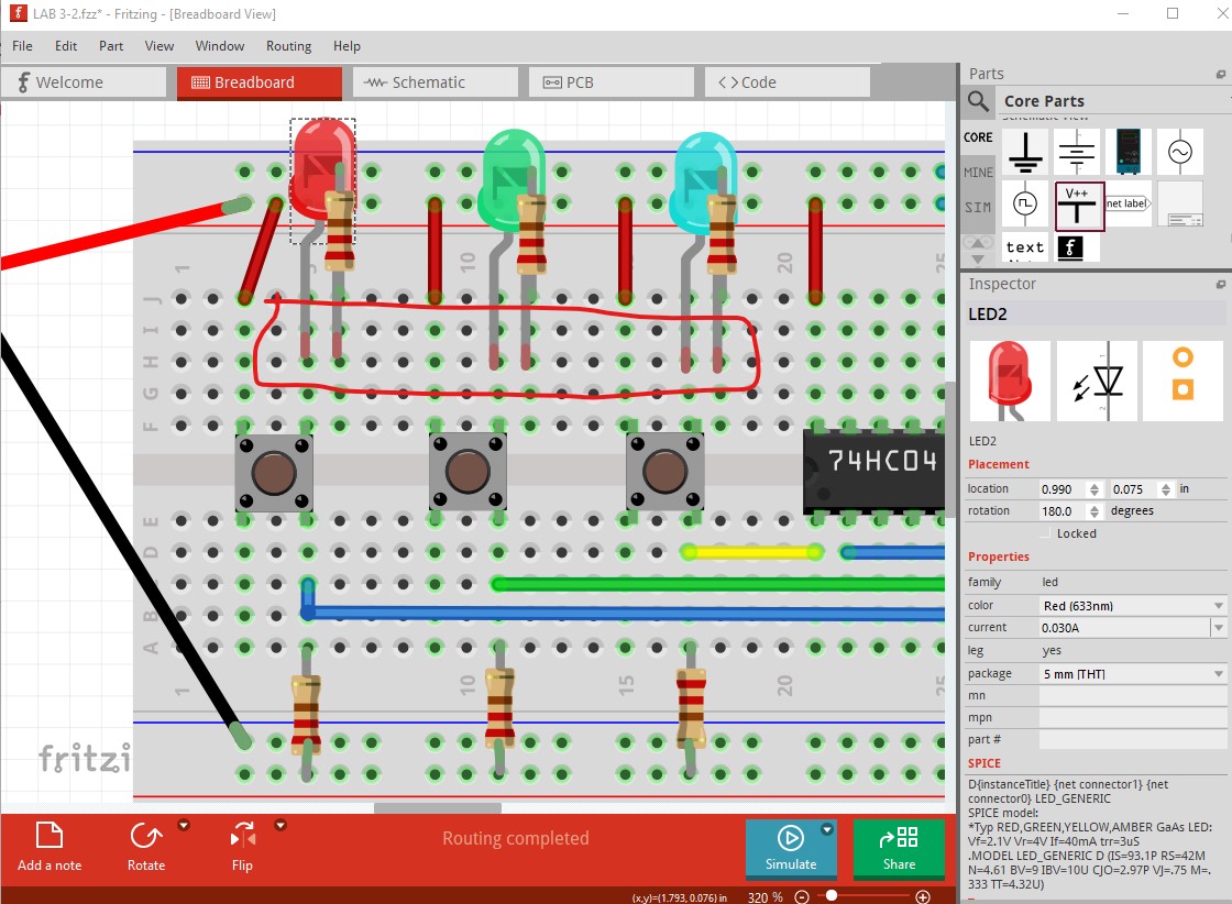
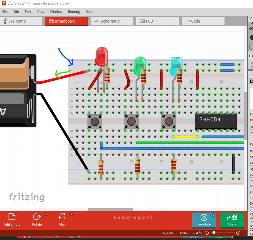
The first thing you need to do is correct breadboard as it is currently incorrect.
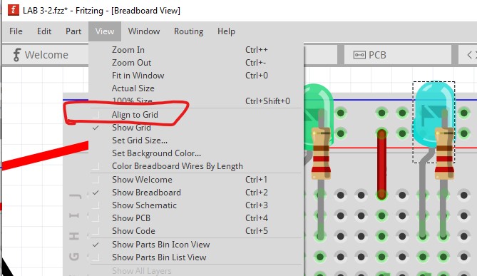
The connections on the LEDs being red indicates they are not connected. To fix that you should enable snap to grid like this
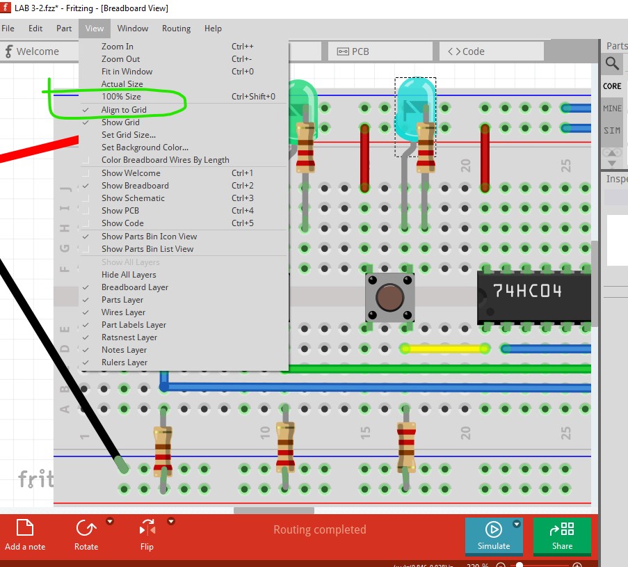
Align to grid is currently disabled (it is enabled by default so you must have done this at some point!) So enable it again.
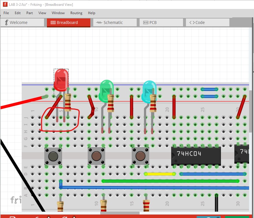
Now move a LED and it will align to the grid
Which indicates the breadboard is not aligned to the grid so the LED does not connect.
Click on the breadboard to select it then move it slightly in both directions which will cause it to snap to the grid and align the LED
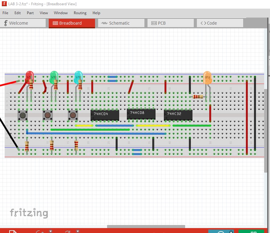
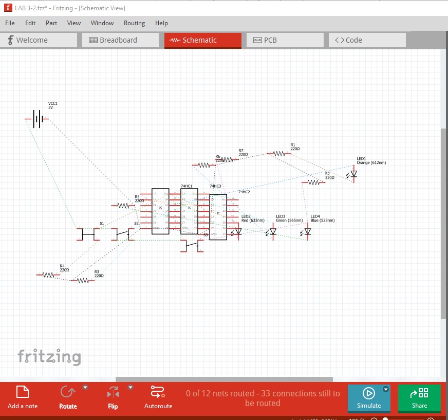
After moving each LED so they snap to the grid they will connect correctly making breadboard connected (but not necessarily correct!.) So then switch to schematic view (which reflects the connections in breadboard with rats nest lines) and route schematic.
Move the components around to a sensible position and then click on and route the rats nest lines to complete schematic. That will give you how the wires in breadboard actually connect at present. If that doesn’t reflect the circuit you intend then you need to change the connections in breadboard until schematic does reflect what you want.
Peter
i already fix the led and routed the schem using auto-route but why is my ic still grey? i check using show unrouted but it say all are routed.
Upload the sketch (upload is 7th icon from the left, the sketch is the .fzz file) and I will have a look at it. If you are trying to simulate it, it likely won’t work as digital ICs typically do not have spice information.
Peter