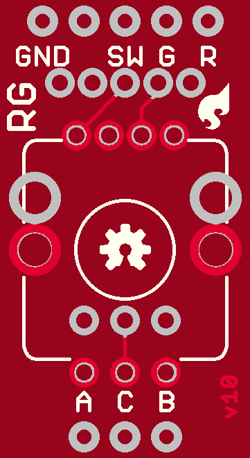
Howdy. I am a highschool student making a part for the first time and I’m having trouble with my PCB. I haven’t had too much time (or will) to reading the super long posts about it as I’m working on this part in-between assignments. Anyways I’m having trouble with the scale of the silkscreen border and the transparency of the copper pins. It is a sparkfun part. I am currently using the exact same size pins that they use on their parts (strait from the toolbox). I’m just not sure how to solve these two issues. Besides that everything else seems to work. My teacher agrees that everything but the PCB is good right now. If I can get any help that would be great.
RG Encoder.fzpz (13.5 KB)
The PNG there is the file from sparkfun on the size of the board to scale.
I would have to disagree that your part is anywhere near correct. Breadboard appears reasonable
schematic is in poor shape
The pins should be aligned on 0.1in boundaries and have terminalId defined so the wire connects at the end of the pin not in the center. There should be leds instead of just wires, the internal wires should connect to the pins.
In Fritzing pcb looks reasonable, but when we look at the gerber output (in this case using gerbv) we see a number of problems
The path for the silkscreen is deficient and doesn’t properly render. There should be holes where the red circles are but the holes are not present. The hole size should be -.038in for a standard 0.1in header, in fact the holes in your board are 0.057in (which is the same size as the pad meaning there will be no copper as it will all be drilled away after etching.) Here the green circle shows a correct header pad with copper surrounding the drilled hole. As you see in the red circled pad on your pcb the drill has eaten all the copper leaving nothing to solder to.
The bottom line is that making parts is a complex process (thus the large amounts documentation that you are ignoring) and pretty much everything needs to be right for the part to work correctly. Looking at the svg files from your part I see a variety of errors, and things that Fritzing doesn’t support that all need to be cleaned up to make a correct part. The pcb svg is in an older format (which is still supported) and is likely one source of error. It also has style definitions which are poorly supported in Fritzing and thus unwise to use unless you have a lot of experience. The bottom line is you likely need to read some of the documentation on making parts to make progress in this endeavor.
Peter


