I need some help with creating a custom pcb layout. PhoenixContact is providing a .stp file and I’m not familiar enough in creating a .svg file for using it in fritzing.
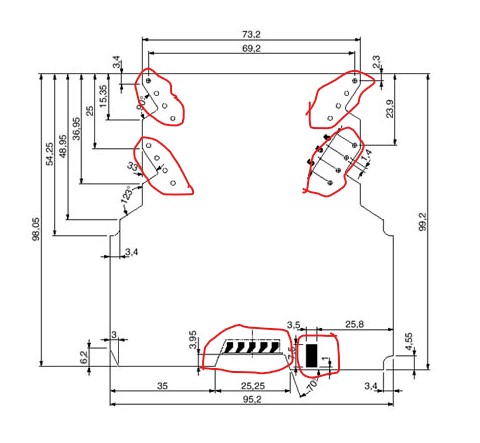
The stp file likely isn’t helpful (and the link to it doesn’t work.) What we would need is a list of the connectors names (I’m assuming the pads aren’t used for anything which may be incorrect!) This drawing from the web site should be enough to make a part but there is no data about what the connector names or purpose are which is required to make a part.
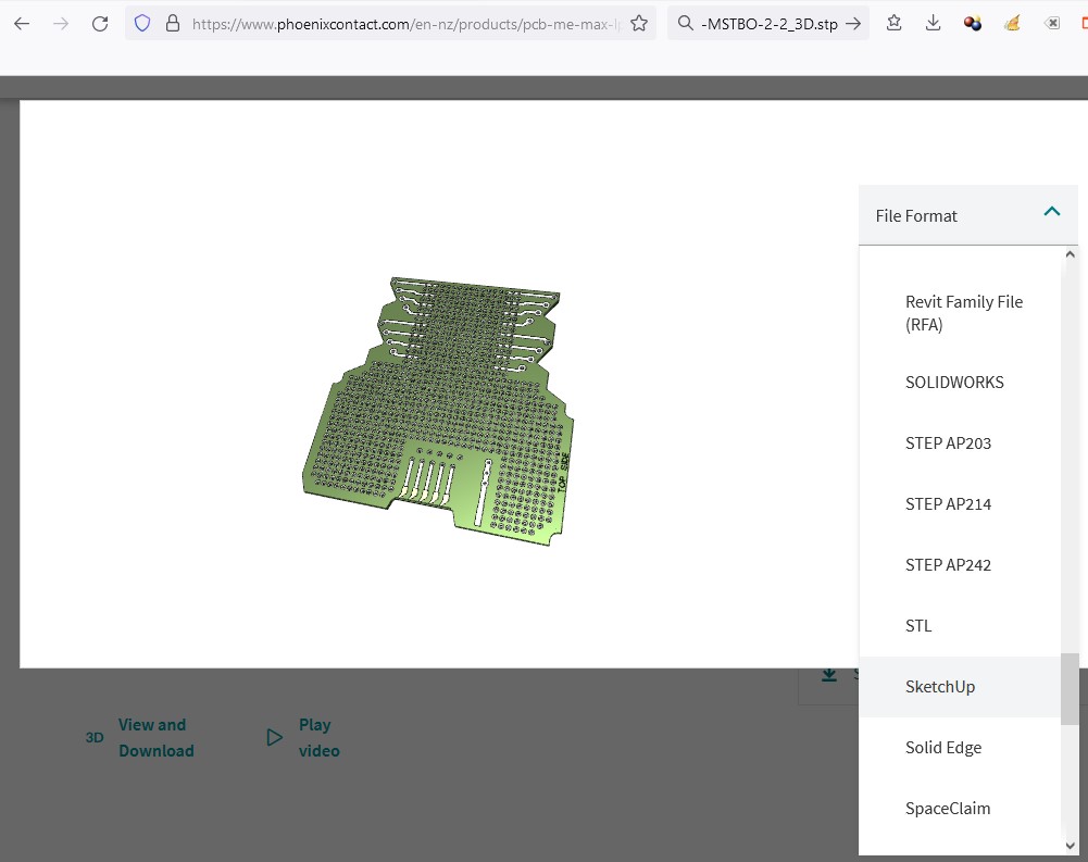
(one of the step files may be what is needed, but I know nothing about .stp to tell which one!) It appears that freecad will convert from .stp to .svg and given an svg I can covert it in to what Fritzing wants.
edit:
OK I downloaded the step AP214 file which gives me a stp file and will see what FreeCad will do with it.
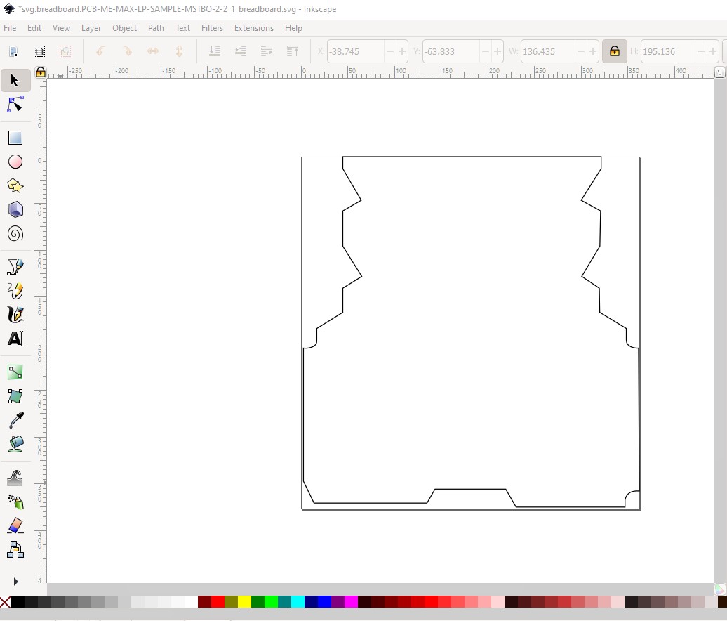
OK, assuming I understood correctly this part should do what you want. It has the board outline in breadboard and pcb but nothing else. The path was made from the measurements in the mechanical drawing jpg and checked against the pdf image on the web site:
which is what is in breadboard and pcb in this part. Unzipping the .fzpz file will get you the pcb svg file which I think is what you want. You would need to print out the pcb footprint at 1:1 scale and compare the printout to a real board to make sure the footprint is in fact correct though!
@vanepp It should be safe to just upload svg files now. A patch to the forum software a while back fixed the issue with rejecting small images. This one was probably big enough to work even before the fix.