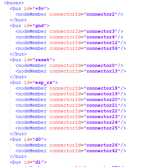
Also, in my .fzp file, I have done this to electrically link all the pins that are on the same net:
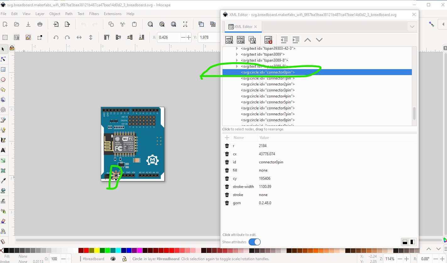
As long as that matches the definitions in the fzp file that will work. What is desirable though is that connector numbers start at 0 and go up in sequence. Pin numbering as you describe is usually from Eagle2Fritzing which converts Eagle files to Fritzng. It uses the pin numbers that Eagle provides often don’t match what is desirable in Fritzing. The usual convention in Fritzing is start with connector 0 at the bottom left (where pin1 on an IC would be.) That is what I did in the breadboard in the [Makerfabs WiFi Shield-fixed-breadboard.fzpz posted above in this thread. The connector numbers in the .fzp file need to match that and so do the connector numbers in schematic and pcb svgs. As noted any connector numbers that are consistent between the svgs and the fzp will work, but there are sometimes problems with the displayed pin description from the fzp file if the pins are not in sequence so it is preferable (but not required to work) that the connectors start at 0 and go up in order.
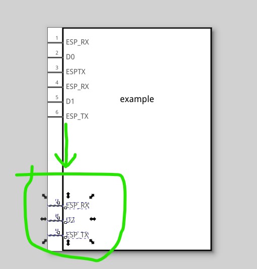
That is handled by the bus definition in the fzp file (this is known as Internal connections in parts editor.) The idea is that all connectors in a bus are internally connected in the actual board (as would be the case in this instance.) There is a complication in schematic in that it will only allow a single connection to a network so if you try and connect two pins in schematic when there is already a connection to the same two buses else where in schematic it will not make a connection (which is confusing if you don’t know why it is happening.) One solution to this is to overlay all the connectors in a bus in schematic on top of each other (setting stroke and fill to none on all of them except 1) so there is only a single connection in schematic. That won’t work well here so I would usually display all the bused together pins in schematic in a row like this so that jumpers can be set to document how the board is connected (which can’t easily be done with the current schematic)

here the pins marked esp_rx and esp_tx are all bused and are intended to be jumpered to the dx pin in the center (a connection to either esp_rx opr esp_tx) the extra space on the rectangle it to allow them to be moved to separate them like this
ending up with this
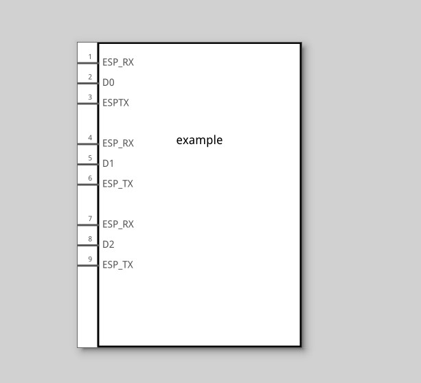
here a “jumper” (implemented by a wire) will be used to connect the ESP_RX or ESP_TX pin to the Digital pin associated with it. It isn’t perfect in that it would allow multiple connections (which would short I/O pins together which would be bad!) but it is best we can do.
Yes, in most cases (it is possible to suppress pins in a view just not usually a very good idea!) all pins need to be defined in all views if they are defined in the fzp file or the part won’t work (Fritzing will cover the part in a red rectangle indicating there are undefined connectors present!)
This looks mostly correct. You don’t need (but it won’t hurt anything I don’t think) the +5V bus as it has only one node member and thus isn’t a bus. The rest look correct as long as they correspond to the connector definitions on the board. Hope this helps, if not ask about what isn’t clear!
Peter
When it is all said and done, is there a rule about taking all the files with the huge hash at the end and removing it? I know it means editing each file and making sure the names all match, but it would seem much nicer to have part.makerfabs_wifi_shield.svg, makerfabs_wifi_shield.fzpz, etc. instead of part.makerfabs_wifi_shield_9f18c39a58cb2729{…}.zyz
I would think “master” versions of parts should have a simple name and if someone later edits it, it can create all those versions separated by the unique hash code appended to the filenames.
Fred
There is a naming convention for files that are used in the core parts. For the user created and loaded parts, the ‘rule’ is that the file names must be unique across all parts loaded in Fritzing. That guid (hash) is Fritzing’s way of cutting way down on the likelihood that 2 different people modifying the same part still end up with unique file names. With parts that are created outside of the core parts, there is no place to look for a master version. Even if there were, 2 different people tweaking it would each end up with a version 2, which would conflict if someone else tried to load both of those version 2 files.
1 Like
While @microMerlin is correct, what used to happen is the guid (which is aimed to be globally unique) was removed when a part is added to core parts (after a check that the result is unique). I believe current practice is to leave the guid in place, but that said a name will work (and is what I usually do) and given that not many people are making parts the chance of a collision don’t seem to be very high (and a run through parts editor will fix it!)
Peter
Peter