I would like to request some help to create this part:
Could someone help me pls?
Here is the Datasheet:
This part should do what you want.
pico-gpio-expansion.fzpz (19.3 KB)
by itself it doesn’t look like much (nor is it particularly useful)
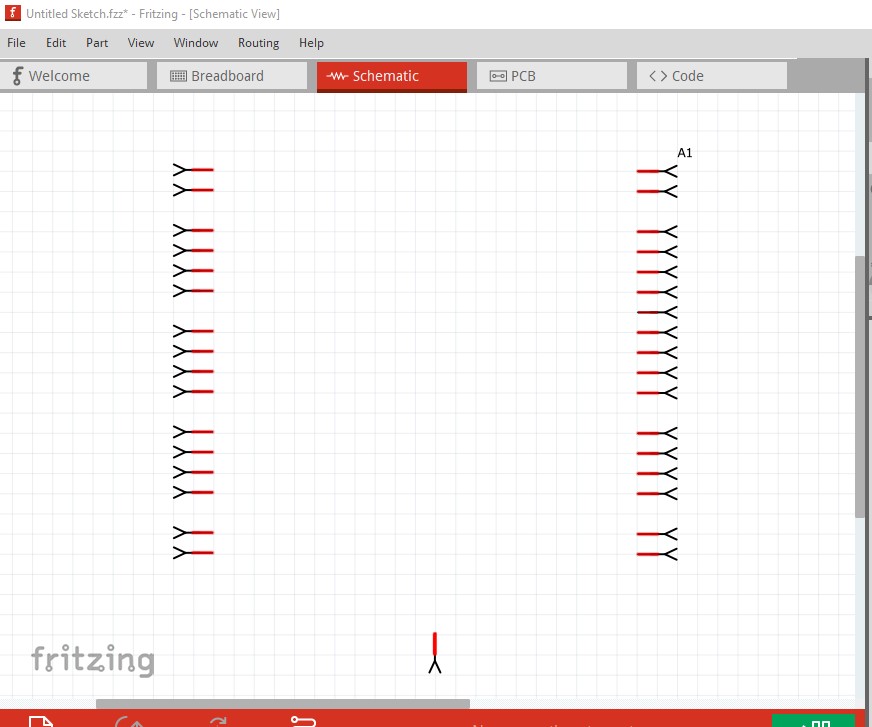
but it isn’t meant to be used by itself. Add the pico tht part then drag it over the pins in breadboard
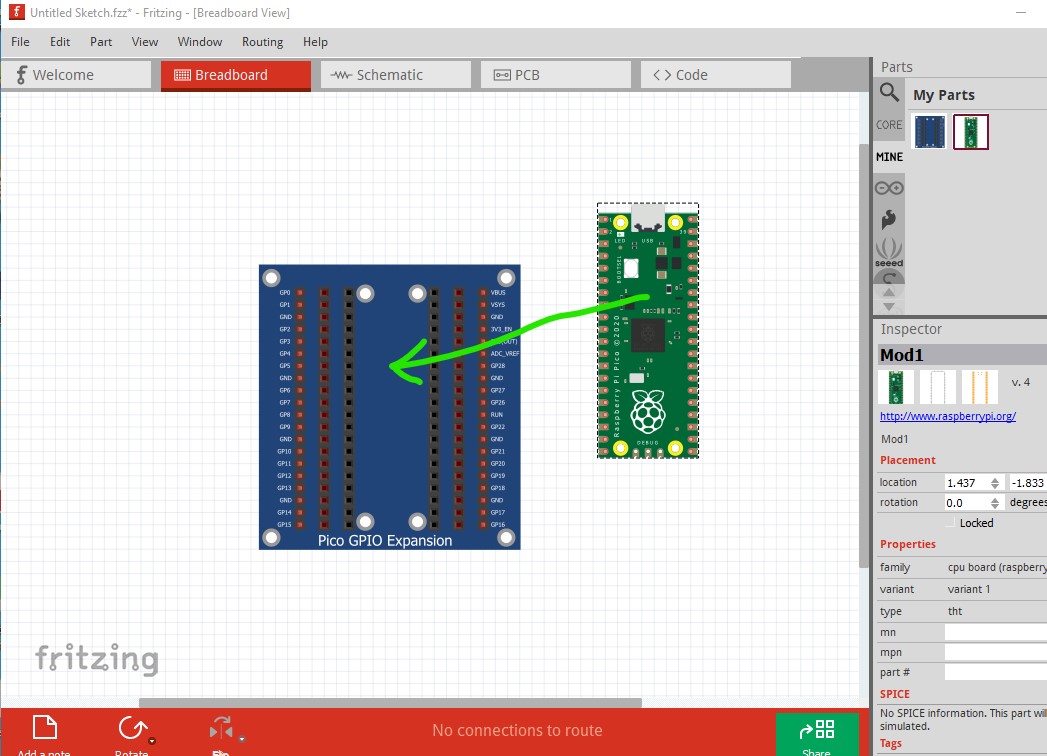
until the pins all go green (indicating a connection)
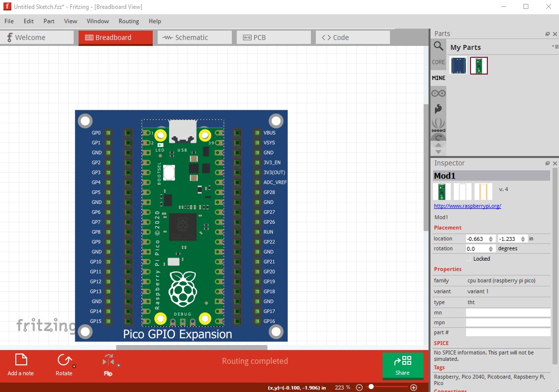
then it is much more useful, since the pico schematic appears and is connected to the other pins.
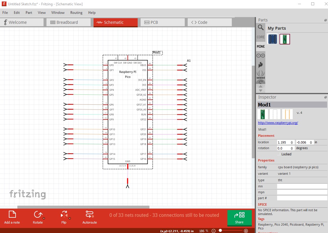

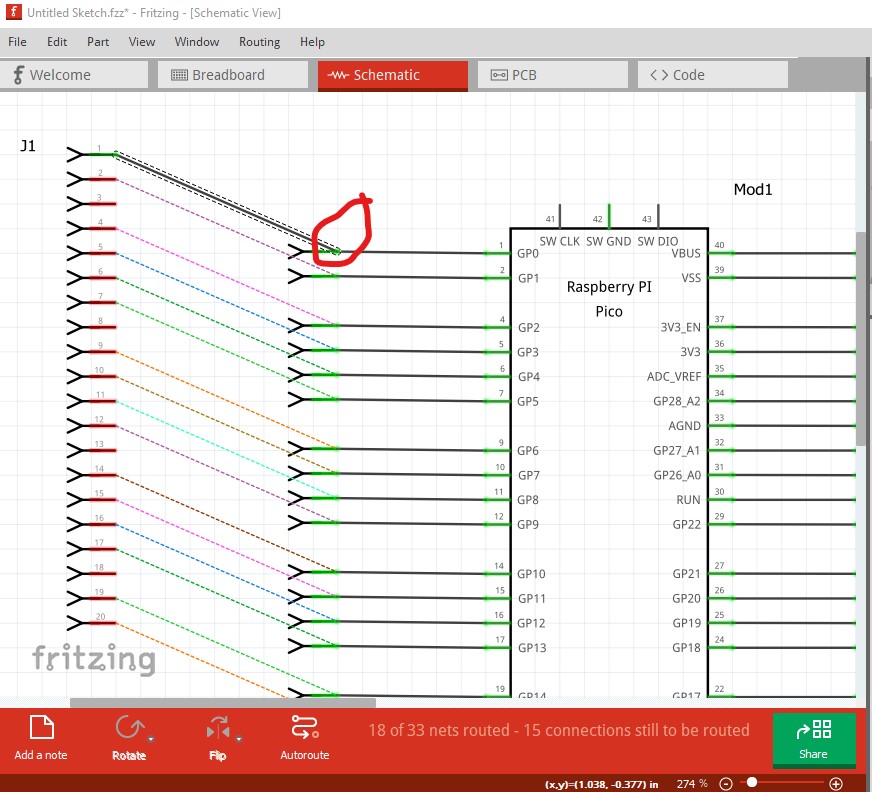
connecting a header to the pins in breadboard reflects in to schematic.

the pins are not aligned quite correctly but it functions.
’
Peter
1 Like
Thanks Peter
Really appriciate your work and support ![]()
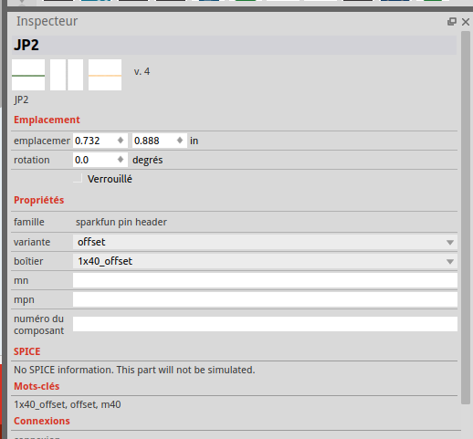
@vanepp Can you point me to the Header part you used on the expansion board pls?
It is a 20 pin generic header copied in to the svg via copy/paste and with the pins renumbered.
Peter
I cant see it in fritzing there is only the single line with 16 or 40 but not 20.
Could you send it to me?
That is because it is a generic header, you need to specify the size in Inspector.
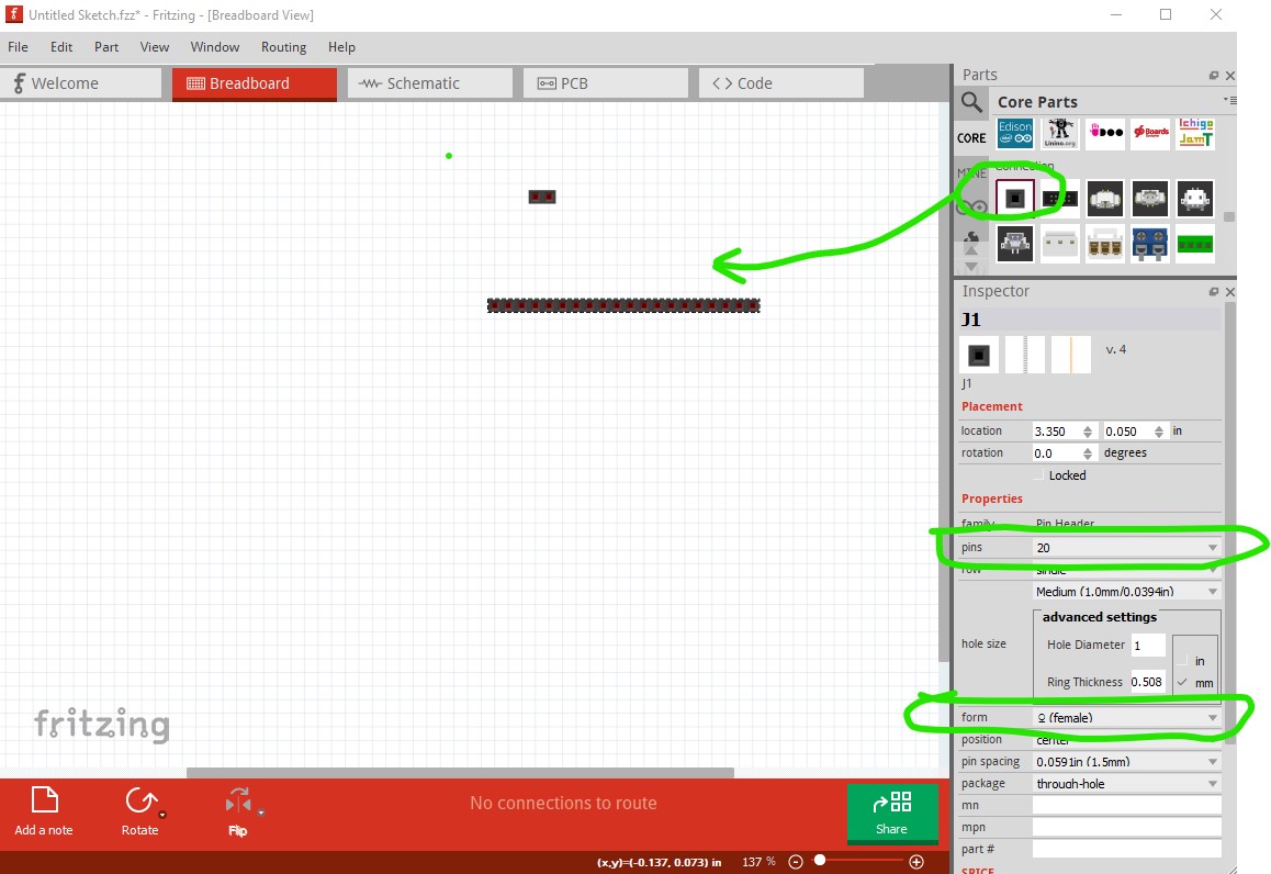
drag the 2 pin version in to a sketch, then in Inspector (the lower right window) select the number of pins, number of rows and sex (male or female, both are used here) you want. Right click on the part and select parts editor then File->save as new part to create a new part in the mine parts bin, right click on that and select export part to write a .fzpz file to the file system, then unzip that to get the .fzp and .svg files for the part.
Peter
it isnt showed on my fritzing install
nvm i was using a specific header not the one in core parts
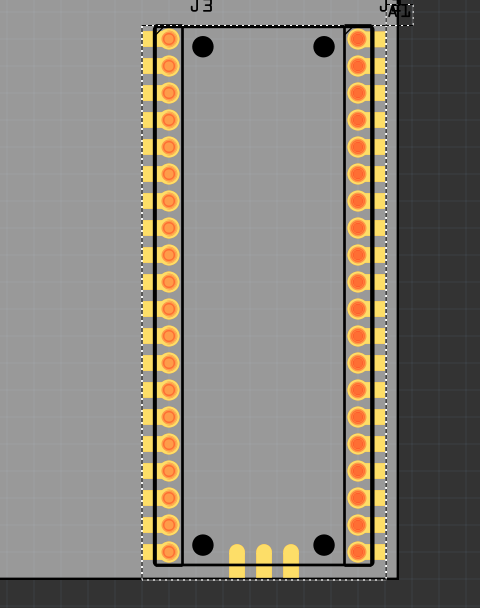
im trying to use these headers in pcb mode to connect the pico to the board.
When I go in pcb i get this:
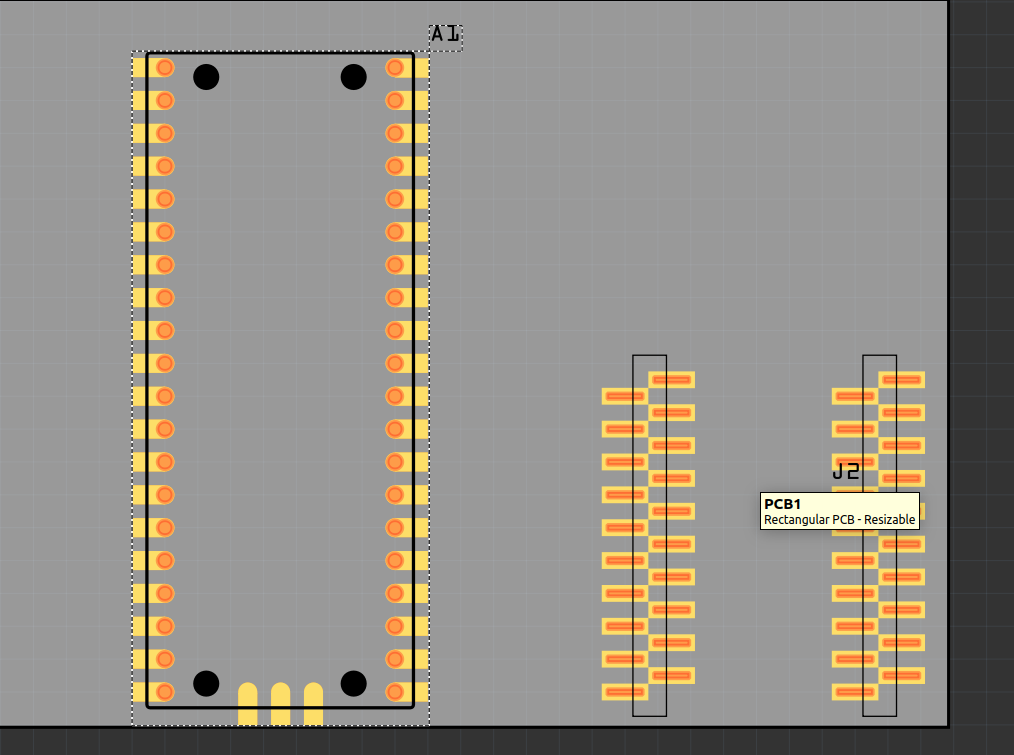
is it normal that it is smaller than the pico?
NVM IM DUMB sorry i choosed the wrong, im still figuring out fritzing
You are trying to use a Sparkfun single size header not the generic connector. You need to drag the generic connector from core parts in to the sketch (Inspector will only work on parts in a sketch) then change that.
then you need to select the connector in a view (any view) to make Inspector able to change its parameters. The Sparkfun connector you are trying to use is both SMD and appears to not be a 0.1in pitch. The default generic connector is through hole and 0.1in pitch which is what the pico wants.
Peter
is it normal that in pcb mode,the pico h part you made is aligned on the headers
but the pico w is not?

Yes in so far as placement is basically random. You need to move the pico and the headers to where you want them (the parts can also be on top of one another os the headers may be overlapping and the second one won’t appear until you move the first one!)
Peter