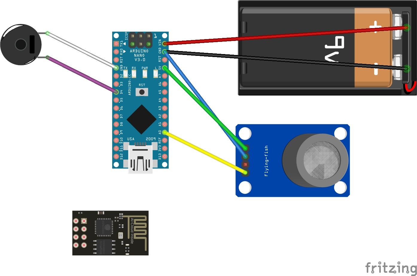
You shouldn’t power an ESP-01 from the 3.3V output of an Arduino Nano: it consumes up to 200mA while that pin produces 40mA maximum.
The ESP-01 pins brought HIGH should be done with a 10K pull-up resistor instead of directly.
ESP-01 RX/TX pins work at 3.3V and it’s not clear (depends on where you read it) if they are 5V tolerant so, to be on the safe side, I will use a voltage divider (18K+10K) for the RX pin on the ESP-01 (TX is fine as the Nano will “understand” 3.3V logic).
There are two level translation options here (a third, easier than either of these, would be to use a 3.3V nano as it won’t need level translation!) The resistor method is shown, a faster alternative is the 74ahc125. Its inputs (only the ahc version though!) are 5V tolerant) and will thus level translate at full speed (the resistor network is slow!) There is an external power supply supplying 3.3V to avoid the current limitation on the Nano (which I should have remembered!) And finally here is the sketch this time.
edit: missed the ground on the ESP01, corrected here!
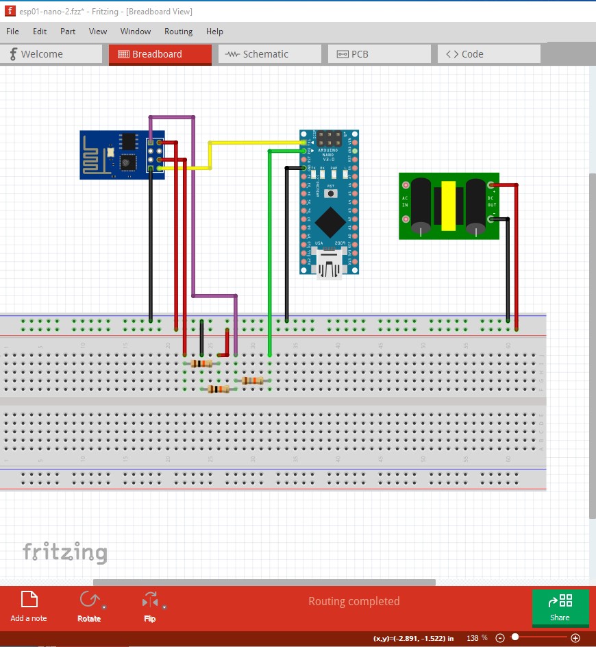
edit2: removed the 74ahc125 and corrected the wiring as rx did not connect to the resistor.
Sorry but this schematic confuses me? is it correct? (R3 is disconnected, purple wire also…). Unless both options are there so “you have to choose one before”… I’ll suggest separated schematics to be simpler/clearer
Voltage dividers work fine for these “slow” speeds and require less components and wiring. You have actually the option to use a proper “lever shifter” like this one in critical scenarios, but I never needed one myself in any practical case…
No it isn’t correct. R3 should have been connected. I replaced both the image and .fzz with one that should be correct and removed the 74ahc125 entirely.
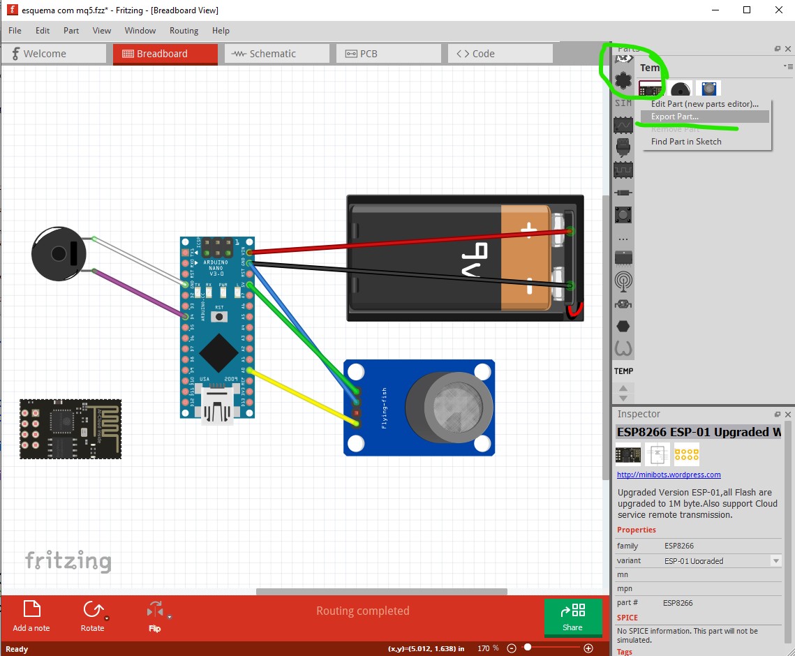
Load the sketch then right click on the part in the temp parts bin and select Export part. Fritzing will prompt you for a file name and directory and then write the .fzpz file for the part there.