Any errors I should look out for?
pcb-upd.fzz (28.6 KB)
A couple of issues:
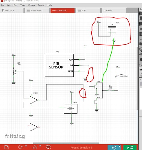
As before the buzzer will always sound. It would make more sense to attach it to the transistors so it only sounds when the LED lights (removing the ground on the buzzer and replacing it with a wire to the transistor collectors.) You likely want current limiting resistors in both transistor bases as well. The PIR sensor and the op amp are likely to provide too much current to the the transistor base emitter junction as it stands (one resistor each where the two red circles are, a 220 ohm should be enough I expect.) The current connection will limit the output to 0.6v for both the op amp and the PIR and may damage their outputs if the current draw is too high.
edit:
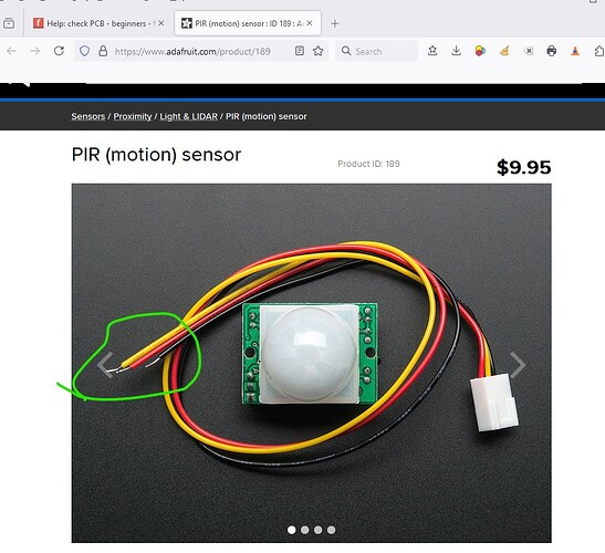
A late thought, the PIR seems likely to be much larger than the silkscreen outline in pcb shows. You need to be sure it is small enough to physically fit in that space if it is intended to mount on the board. That shouldn’t be an issue if it is being connected via wires to the board though.
Peter
I’m not sure what buzzer you’re referring to, I have eliminated it from my circuit entirely. Oh, if you’re referring to what’s labelled “TRM”, that’s the 2-pin screw terminal I intend to use to supply the PCB with power. What do you think?
You likely want current limiting resistors in both transistor bases as well.
will do.
A late thought, the PIR seems likely to be much larger than the silkscreen outline in pcb shows. You need to be sure it is small enough to physically fit in that space if it is intended to mount on the board. That shouldn’t be an issue if it is being connected via wires to the board though.
Ah that makes sense, in the PCB view, many components which appear to be similar in size to the PIR are actually tiny in real life in comparison to the PIR, hoping it fits though.
Yep I mistook that for the buzzer from the earlier circut so ignore that comment.
From the Adafruit data sheet it looks like it connects via wires so assuming you unit is the same it should work OK as is.
Peter
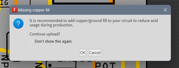
They are right less etching saves them money and helps the environment but the circuit will work as is without the copper fill so it is up to you.
Peter


