Hey guys, don’t know where else to turn.
I created a Custom PCB shape in inkscape uploaded it to Fritz where it looks normal until either I try to add a copper ground layer or export it as a Gerber.
Hey guys, don’t know where else to turn.
I created a Custom PCB shape in inkscape uploaded it to Fritz where it looks normal until either I try to add a copper ground layer or export it as a Gerber.
There are a number of bugs in this area, but your best bet is to upload the sketch (the .fzz file, upload is the 7th icon from the left in the reply menu.) so someone can look at it. There are a number of tutorial posts by @opera_night that are also worth looking at.
Peter
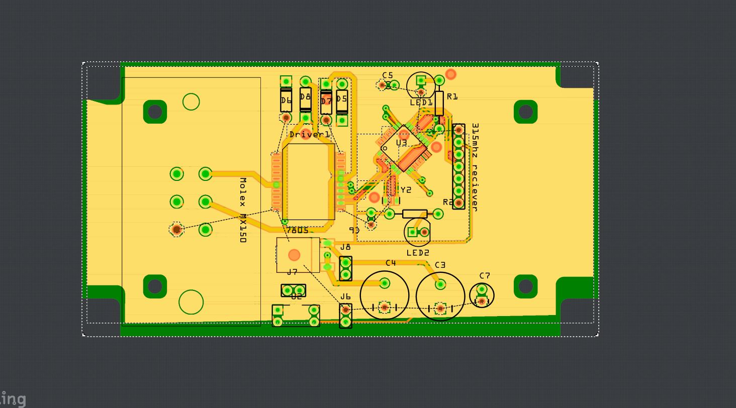
Exhaust controller V4.fzz (32.2 KB)
added File
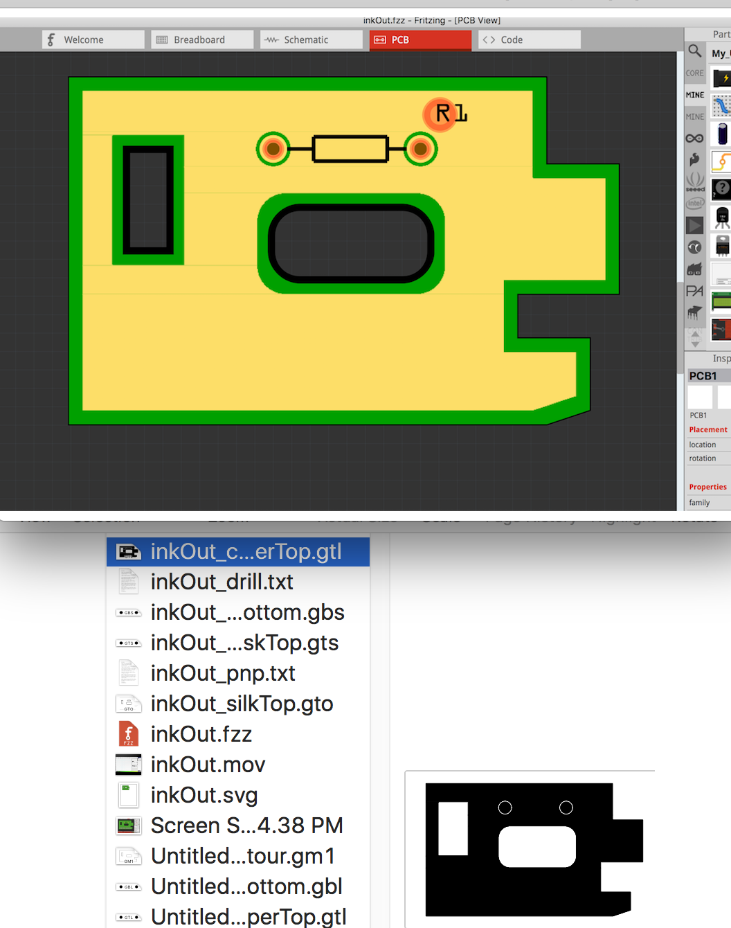
If not already done so, let me suggest looking at my recent Tutorial Post and starting with a simple shape, loading it into Fritzing and add one or two simple parts and a Copper fill area.
Below shows the PCB from the Video tutorial with Copper fill added to the Top layer, just to confirm for your that it works.
Ensure you place the copper fill where it won’t cause problems - that may require some fussing - Fritzing is not perfect… thus, start with a clean test board, no cutouts…
Without even looking at the outline file, DRC (routing->design rules check) is already unhappy with the border. The first two entries are indicating (via the red line on the bottom of the pad circle) that it thinks the pad is too close to the edge of the board (which should be the green underlay which is not too close. This probably indicates the outline file is not correct (not that I know what to do about that, I have never managed to get cutouts to work even with @opera_night 's tutorials  .) For any smart people willing to help with this here is a copy of the boardoutline.svg file (recovered from the .fzz file):

first thing I would do is ungroup and regroup to remove this transform:
     </metadata>
 <g transform="translate(0,-239.5)">
  <g id="layer1">
   <g id="silkscreen">
as Fritzing sometimes doesn’t like transforms (especially in this area.)
Peter
Peter, I don’t know why you’re having trouble making cutouts; as seen in my tut’s, it’s easy and I’m not doing any behind the scene magic.
I guess I could imagine that between my using a Mac, Fritzing 0.9.3 beta and Inkscape for the Mac, some incompatibilities could arise. But, it’s so simple to do the Handmade cutouts, as a last (but, simple) resort.
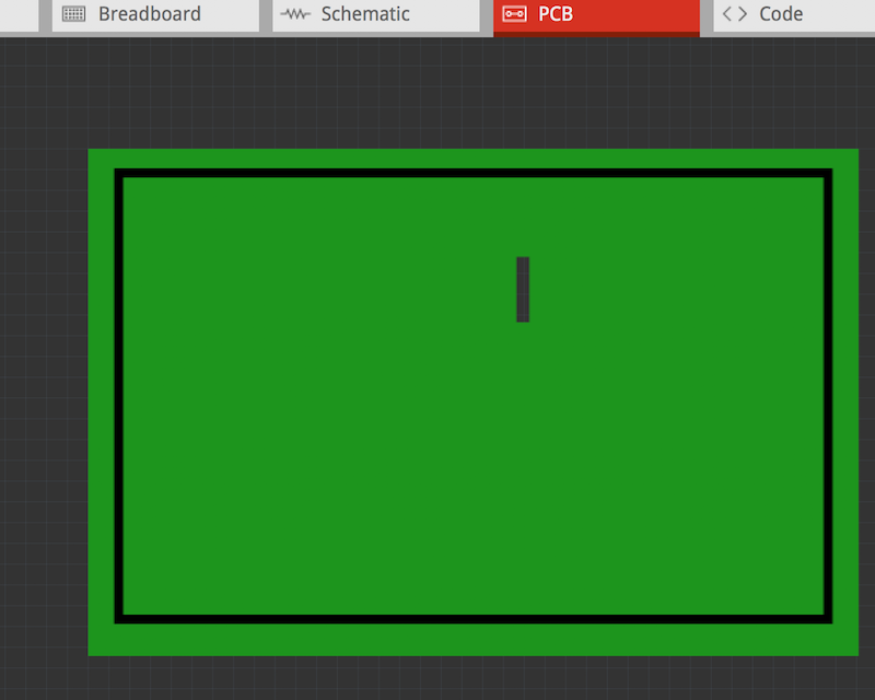
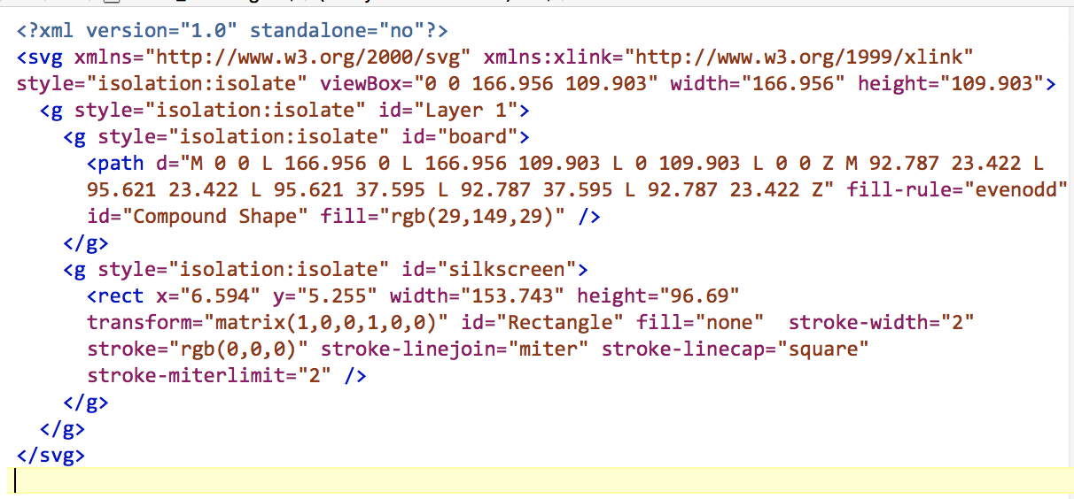
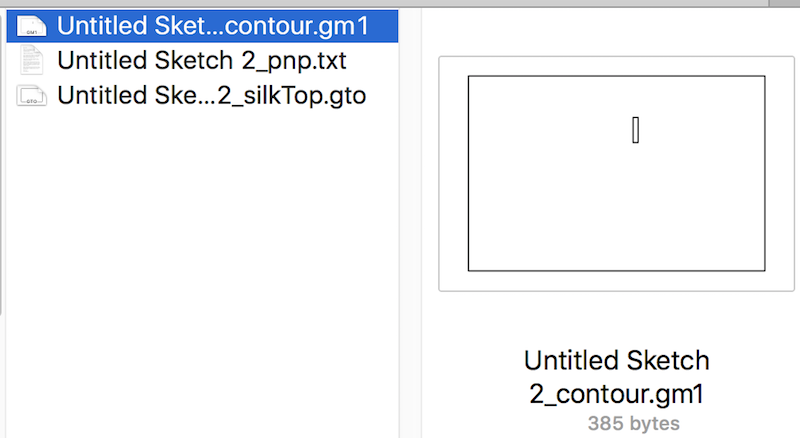
Below are:
Image of simple rectangular board with One cutout
Image of the SVG xml
Image of Contour gerber
Frtizing file
(note: I did Not bother to draw the Cutout on the Silk layer so, it won’t be there.
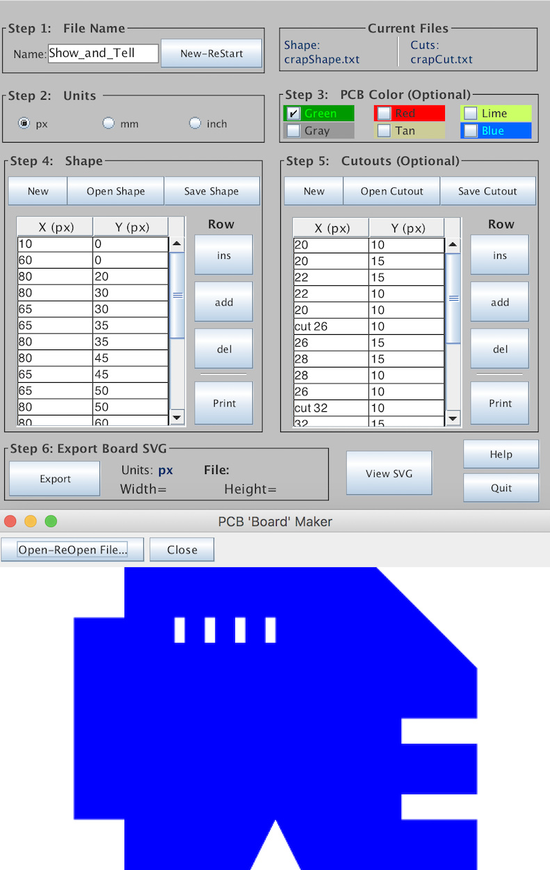
Also, as you may recollect, after extensive testing with various graphics software, I tend to avoid the most troubling ones - particularly, Inkscape but, all have some issues.
So, though I usually use Gravit, for Fun, I did write my own App, in Java with embedded viewer - works great, the last screenshot. Simply define the outer perimeter and the cutouts… Perhaps someday I’ll post it to some site…)
4peter.fzz (1.2 KB)
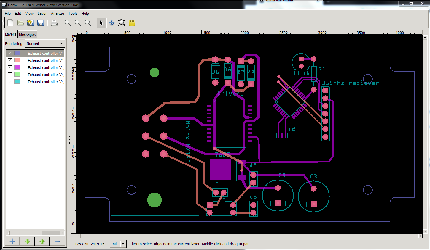
You are running in to Fritzing bugs. There is a solution, but it it isn’t easy. You would need to build 0.9.5 (or in this case current head) from source. Kjell fixed at least 5 bugs in gerber generation about 6 months ago and 0.9.5 renders like this (the gerber output under gerbv):
the traces are still a mess but the outline is correct.
Peter